Vaporizer and deposition system using the same

a technology of vaporizer and deposition system, applied in chemical vapor deposition coating, electric discharge tube, coating, etc., can solve the problems of insufficient flow of raw gas, discharge outlet, and liquid material components, and achieve the effect of improving vaporization efficiency

Inactive Publication Date: 2011-07-28
TOKYO ELECTRON LTD
View PDF4 Cites 13 Cited by
  • Summary
  • Abstract
  • Description
  • Claims
  • Application Information

AI Technical Summary

Benefits of technology

[0022]According to the present invention, it is possible to prevent the discharge outlet of the liquid material from being clogged by accretions, and also to improve the vaporization efficiency at the vaporization chamber, since the discharge outlet of the liquid material can be partially heated and separately from the vaporization chamber.

Problems solved by technology

However, in a conventional vaporizer in which the flow of the carrier gas is formed near the discharge outlet that discharges the liquid material as described above, there was a problem that the components of the liquid material, depending on the kind of liquid material, react with the small amount of moisture included in the carrier gas, and are solidificated.
Therefore, there also is a concern that if the liquid material including the composition that is easy to react with the moisture as described above is discharged from the discharge outlet, the product (an oxide) made by the reaction with the moisture included in the carrier gas flowing near the discharge outlet is attached and deposited to the discharge outlet, thereby blocking the discharge outlet by the undesired accretion.
With this, an enough flow of the raw gas may not be obtained.
Additionally, since the replacement or cleaning of the nozzles should be frequently needed, the throughput of the process is decreased.
Also, in the case where the carrier gas is flowed between the discharge outlet of the nozzle and a diaphragm and vaporized as disclosed in patent document 1, if the entire portion where the diaphragm valve and nozzle are provided is heated in order to improve a vaporization efficiency as in patent document 4, it is undesirable because even the liquid material flowing in the nozzle is likely to be thermally decomposed, as the heating temperature becomes high.

Method used


Image

  • Vaporizer and deposition system using the same
  • Vaporizer and deposition system using the same
  • Vaporizer and deposition system using the same

Examples


Embodiment Construction

[0027]Hereinafter, preferred embodiments of the present invention will be described in detail, with reference to the attached drawings. In addition, throughout the specification and the drawings, same reference numbers are used to represent the components having substantially same functions and configuration, and the description thereof is omitted for clarity.

Deposition System

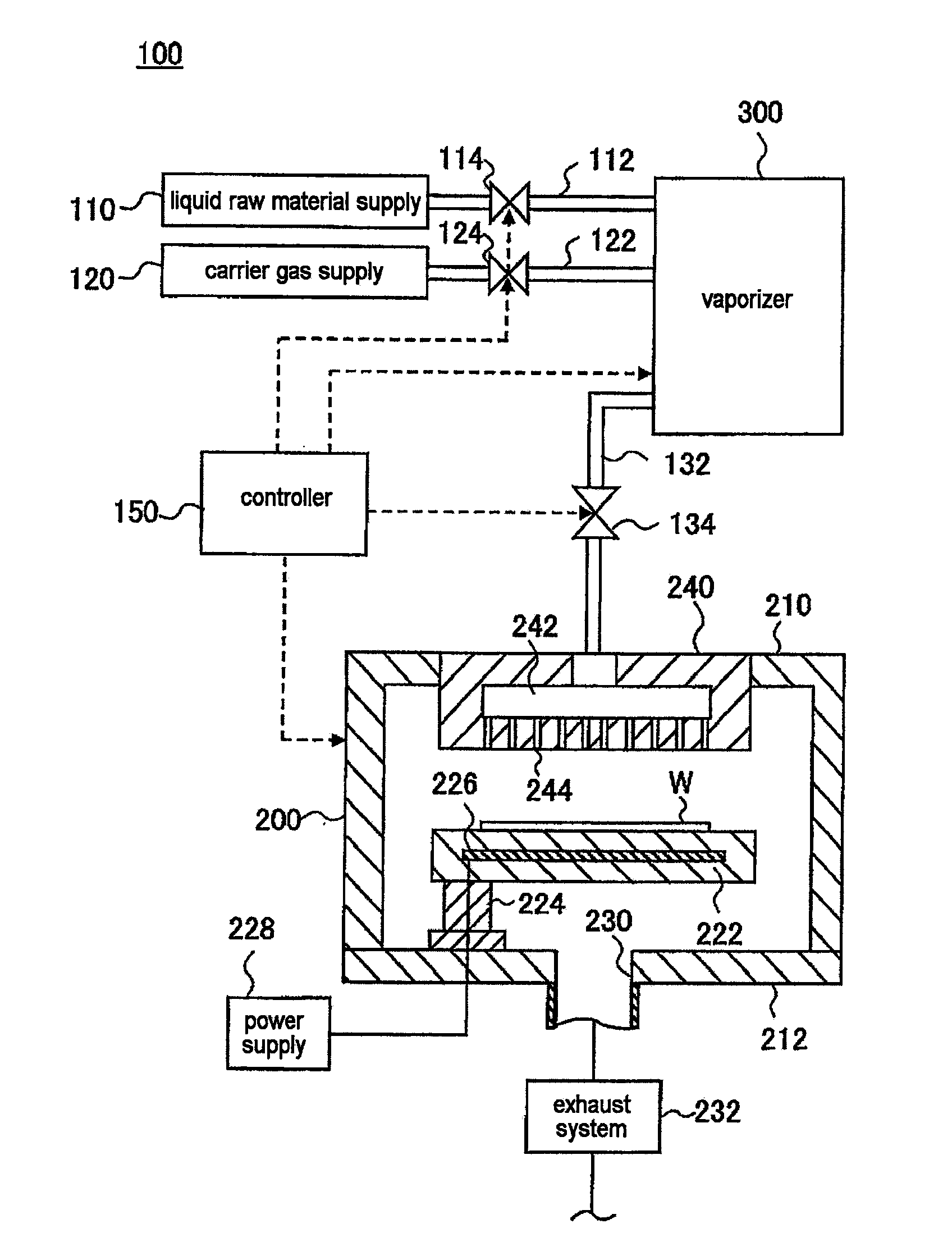
[0028]First, the deposition system according to the embodiment of the present invention will be described with reference to the drawings. FIG. 1 is a view for illustrating an example of the schematic constitution of the deposition system according to the embodiment of the present invention. A deposition system 100 shown in FIG. 1 is configured to form a metal oxide film on a substrate to be processed, for example, a semiconductor waver (hereinafter, “wafer”) W by a CVD method. Deposition system 100 includes a liquid material supply 110 configured to supply a liquid material including an organic compound contain...


PUM

PropertyMeasurementUnit
temperatureaaaaaaaaaa

Abstract

To prevent a liquid material outlet from being clogged with accretion. Disclosed is a vaporizer, which vaporizes a liquid material, discharged from the outlet of a nozzle, in a heated vaporization chamber to produce a raw gas, and which is provided with a cylindrical heated member, which is disposed between the front end of the nozzle and the vaporization chamber so as to cover the perimeter of the outlet, a carrier gas ejection port, which ejects a carrier gas from the vicinity of the outlet, a mixing chamber, wherein the liquid material discharged from the outlet is mixed with the carrier gas, which ejects the mixture toward the vaporization chamber, a first heating part, which heats the vaporization chamber from its exterior, and a second heating part, which heats the heated member from its exterior.

Description

FIELD OF THE INVENTION[0001]The present invention relates to a vaporizer that produces a raw material gas by vaporizing a liquid material and a deposition system using the vaporizer.BACKGROUND ART[0002]In general, as a film forming method for forming various thin films formed with dielectric material, metal, semiconductor and the like, a chemical vapor deposition (CVD) method has been known in which an organic raw material such as an organo-metallic compound is supplied to a film forming chamber to form films by allowing the organic raw material to react with other gases such as oxygen or ammonia. Since the organic raw material used for such CVD method is often a liquid state under the room temperature and a normal pressure, there is a need for the organic raw material to be gasified to be supplied to the film forming chamber. Therefore, typically, the organic raw material in the liquid state is vaporized in a vaporizer to form a raw gas.[0003]For example, according to the patent do...

Claims


Application Information

Patent Timeline
Patent Type & Authority Applications(United States)
IPC IPC(8): C23C16/448C23C16/455
CPCC23C16/4481H01L21/31645H01L21/31641H01J37/3244H01L21/02181H01L21/02189C23C16/448H01L21/0262
Inventor TANAKA, SUMIFUTAMURA, MUNEHISA
Owner TOKYO ELECTRON LTD
Why Eureka
Try Eureka