Thin film transistor, method of manufacturing thin film transistor, display unit, and electronic device
a technology of thin film transistors and transistors, applied in the direction of basic electric elements, electrical apparatus, semiconductor devices, etc., can solve the problems of changing the characteristics of the transistors, and achieve the effect of increasing the size and increasing the mobility
Active Publication Date: 2011-07-28
JOLED INC
View PDF1 Cites 20 Cited by
- Summary
- Abstract
- Description
- Claims
- Application Information
AI Technical Summary
Benefits of technology
[0008]Such an oxide semiconductor may be formed as a film by using sputtering which is advantageous to increase the size. Further, despite an amorphous phase of the oxide semiconductor, the carrier mobility is approximately 10 cm2 / V·s, and it is thus possible to obtain the mobility higher than that of the amorphous Si.
[0014]In view of the foregoing, it is desirable to provide a thin film transistor capable of easily controlling a threshold voltage, a method of manufacturing the same, and a display unit using the same and an electronic device.
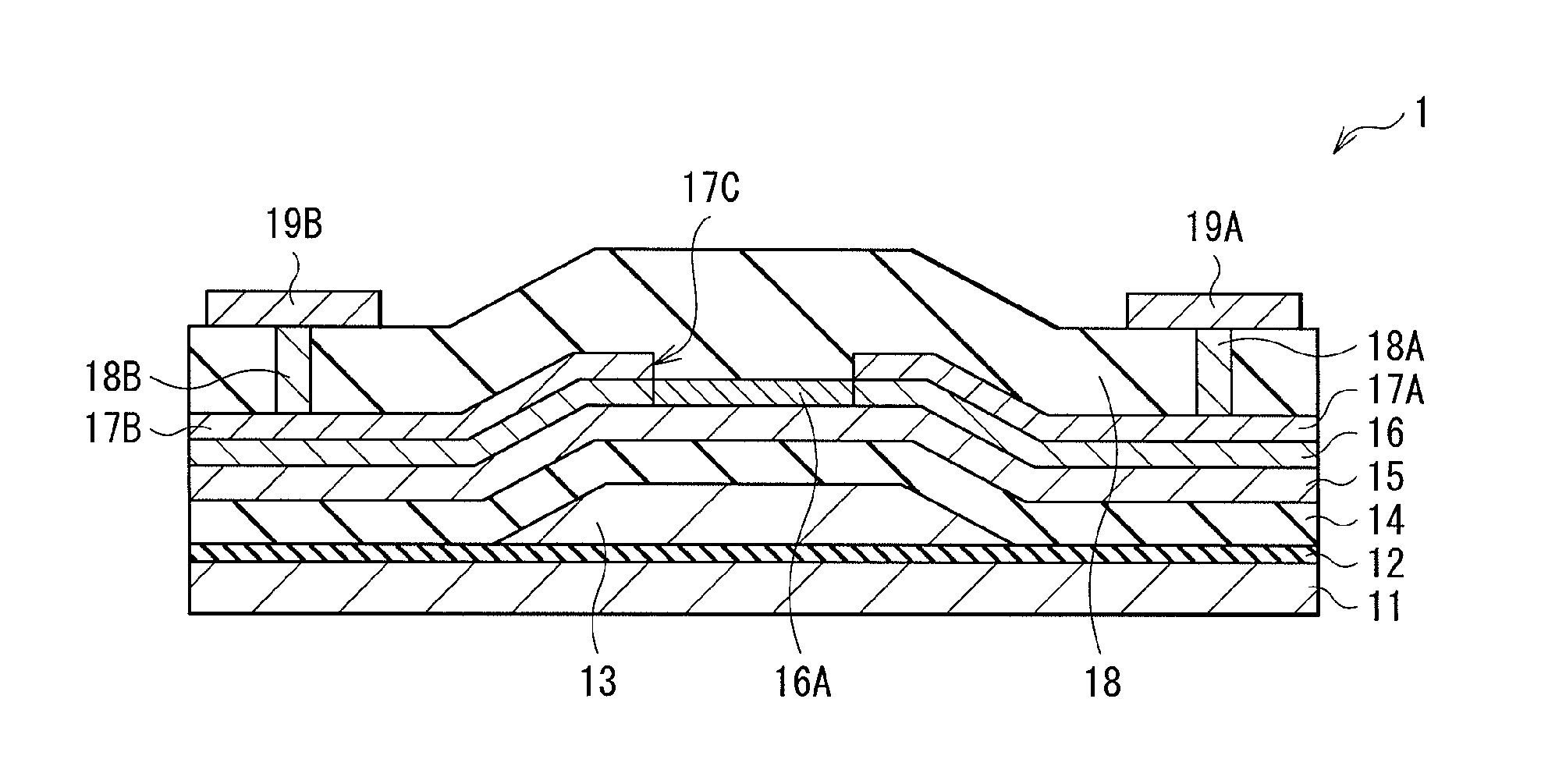
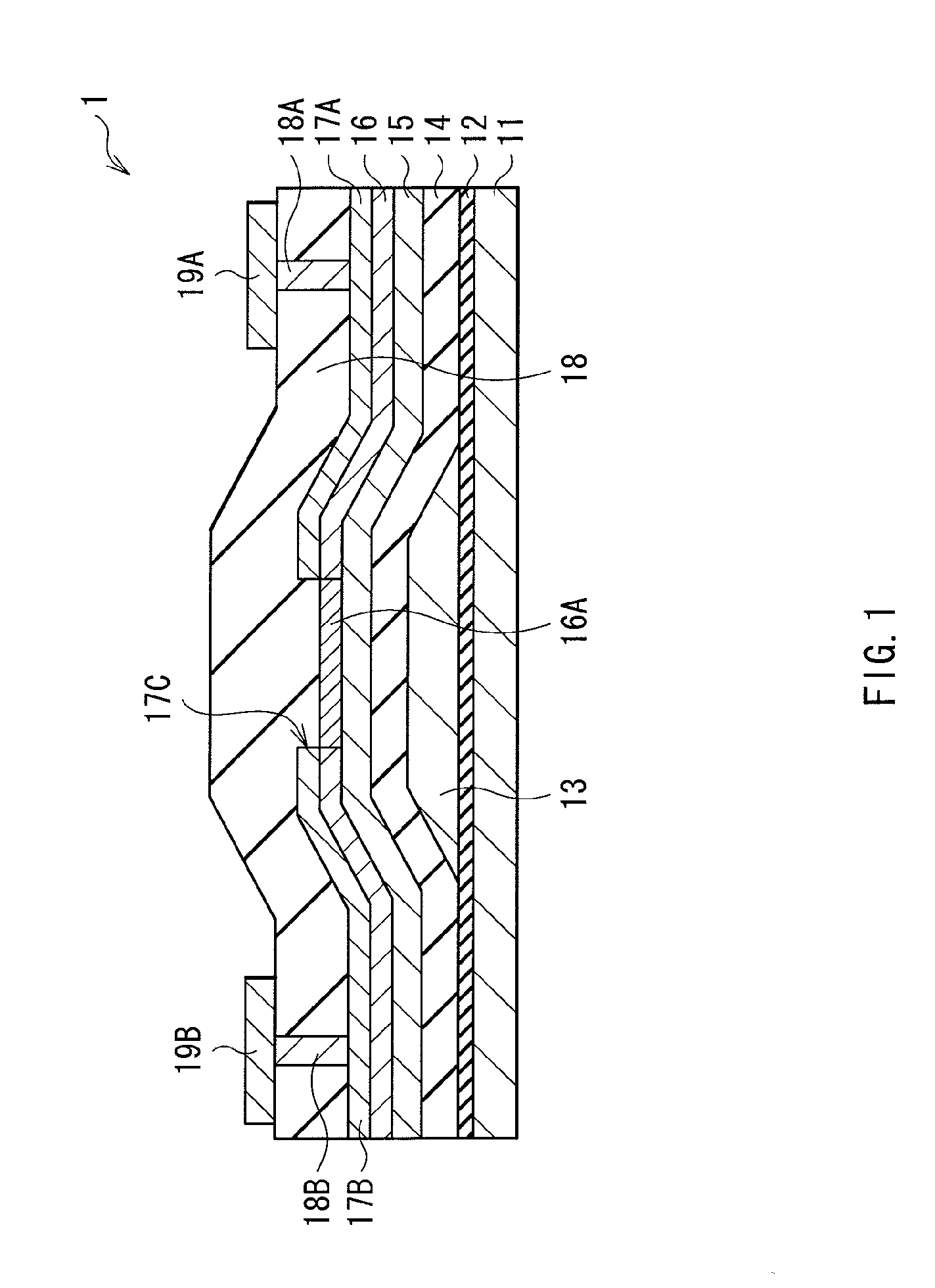
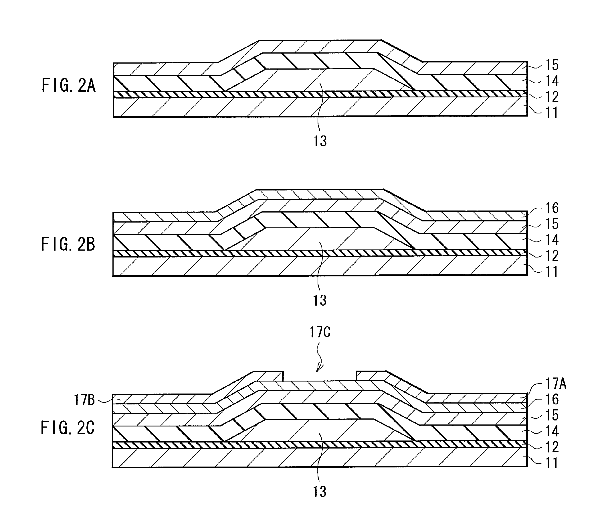
[0020]According to the thin film transistor, and the method of manufacturing the thin film transistor of the embodiments of the present invention, the second oxide semiconductor layer having the polarity different from that of the first oxide semiconductor layer is provided above the first oxide semiconductor layer (on the pair of source / drain electrodes side) forming the channel. Thereby, a carrier density in the first oxide semiconductor layer is reduced, and the threshold voltage may be maintained to be a positive (+) value. In other words, it is not necessary to separately perform other processes to shift the threshold voltage from a negative side to a positive side, such as annealing for a long time, and thinning the oxide semiconductor layer. Therefore, the threshold voltage is easily controllable.
Problems solved by technology
Therefore, in the case where the oxide semiconductor is used as the channel layer of TFT, there is such an issue that the transistor characteristics (transfer characteristics) are changed when the oxide semiconductor layer is in contact with outside air.
Method used
View moreImage
Smart ImageViewing Examples
Examples
first embodiment (
1. First embodiment (example where a p-type oxide semiconductor layer is formed by an oxidation treatment)
second embodiment (
2. Second embodiment (example where the p-type oxide semiconductor layer is formed by patterning)
third embodiment (
3. Third embodiment (example where the p-type oxide semiconductor layer is formed by an impurity introduction treatment)
4. Modification (example of a top-gate type TFT)
Login to View More PUM
 Abstract
There is provided a thin film transistor including: a gate electrode; a pair of source / drain electrodes; a first oxide semiconductor layer provided between the gate electrode, and the pair of source / drain electrodes, and forming a channel; and a second oxide semiconductor layer provided on the pair of source / drain electrodes side of the first oxide semiconductor layer, and having a polarity different from that of the first oxide semiconductor layer.
Description
BACKGROUND OF THE INVENTION[0001]1. Field of the Invention[0002]The present invention relates to a thin film transistor (TFT) using an oxide semiconductor, a method of manufacturing the same, and a display unit including the same and an electronic device.[0003]2. Description of the Related Art[0004]In a flat panel display such as a liquid crystal display and an organic EL (electroluminescence) display, a silicon (Si) material is typically used as a channel layer (active layer) in a drive thin film transistor. Specifically, examples of the silicon material include an amorphous Si and a polycrystalline Si.[0005]However, in the case where the amorphous Si is used as the channel layer, although it is possible to easily increase the size of the display, the mobility of a carrier (for example, an electron) is low as approximately 1 cm2 / V·s, and it is thus difficult to realize high performance of the display. Meanwhile, in the case where the polycrystalline Si is used as the channel layer,...
Claims
Login to View More Application Information
Patent Timeline
 Patent Type & Authority Applications(United States)
IPC IPC(8): H01L29/12H01L21/336H01L33/16
CPCH01L29/7869H01L29/66969H01L29/78696
Inventor TANIGUCHI, SATOSHI
Owner JOLED INC
Features
- R&D
- Intellectual Property
- Life Sciences
- Materials
- Tech Scout
- Unparalleled Data Quality
- Higher Quality Content
- 60% Fewer Hallucinations
Learn More Browse by: Latest US Patents, China's latest patents, Technical Efficacy Thesaurus, Application Domain, Technology Topic, Popular Technical Reports.
© 2025 PatSnap. All rights reserved.Legal|Privacy policy|Modern Slavery Act Transparency Statement|Sitemap|About US| Contact US: help@patsnap.com


