X-ray shield grating, manufacturing method therefor, and x-ray imaging apparatus

a technology of shield grating and manufacturing method, which is applied in the direction of manufacturing tools, imaging devices, instruments, etc., can solve the problem of difficulty in manufacturing an x-ray shield grating having a period in two, and achieve the effect of easy manufacturing

Inactive Publication Date: 2011-07-28
CANON KK
View PDF7 Cites 11 Cited by
  • Summary
  • Abstract
  • Description
  • Claims
  • Application Information

AI Technical Summary

Benefits of technology

[0009]In the method of manufacturing an X-ray shield grating disclosed in Microelectronic Engineering Volume 84 (2007), 1172-1177, a direction of the period of the Si structure which is twice as long as that of the X-ray shield grating is the same as a direction of a period of a structure which is finally obtained by being plated with gold. Therefore, in the above-mentioned method of manufacturing an X-ray shield grating, only a line-like X-ray shield grating having its period only in one dimension may be manufactured, and it is difficult to manufacture an X-ray shield grating having its period in two dimensions (hereinafter, referred to as a two-dimensional X-ray shield grating). The present invention is made in view of the above-mentioned problem, and an object of the present invention is to provide a two-dimensional X-ray shield grating which may be manufactured more easily and to provide a manufacturing method therefor.

Problems solved by technology

Therefore, in the above-mentioned method of manufacturing an X-ray shield grating, only a line-like X-ray shield grating having its period only in one dimension may be manufactured, and it is difficult to manufacture an X-ray shield grating having its period in two dimensions (hereinafter, referred to as a two-dimensional X-ray shield grating).

Method used


Image

  • X-ray shield grating, manufacturing method therefor, and x-ray imaging apparatus
  • X-ray shield grating, manufacturing method therefor, and x-ray imaging apparatus
  • X-ray shield grating, manufacturing method therefor, and x-ray imaging apparatus

Examples


example 1

[0045]As Example 1, an example of manufacturing an X-ray shield grating having a period of 4 μm is described.

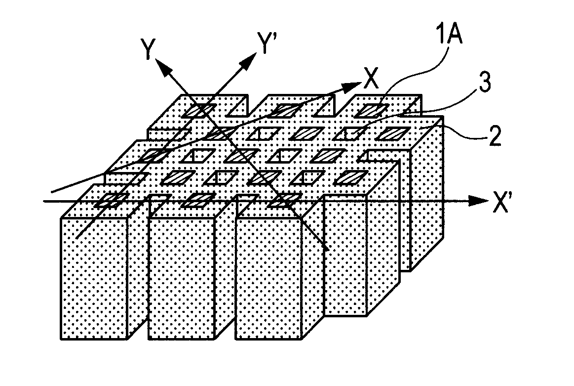
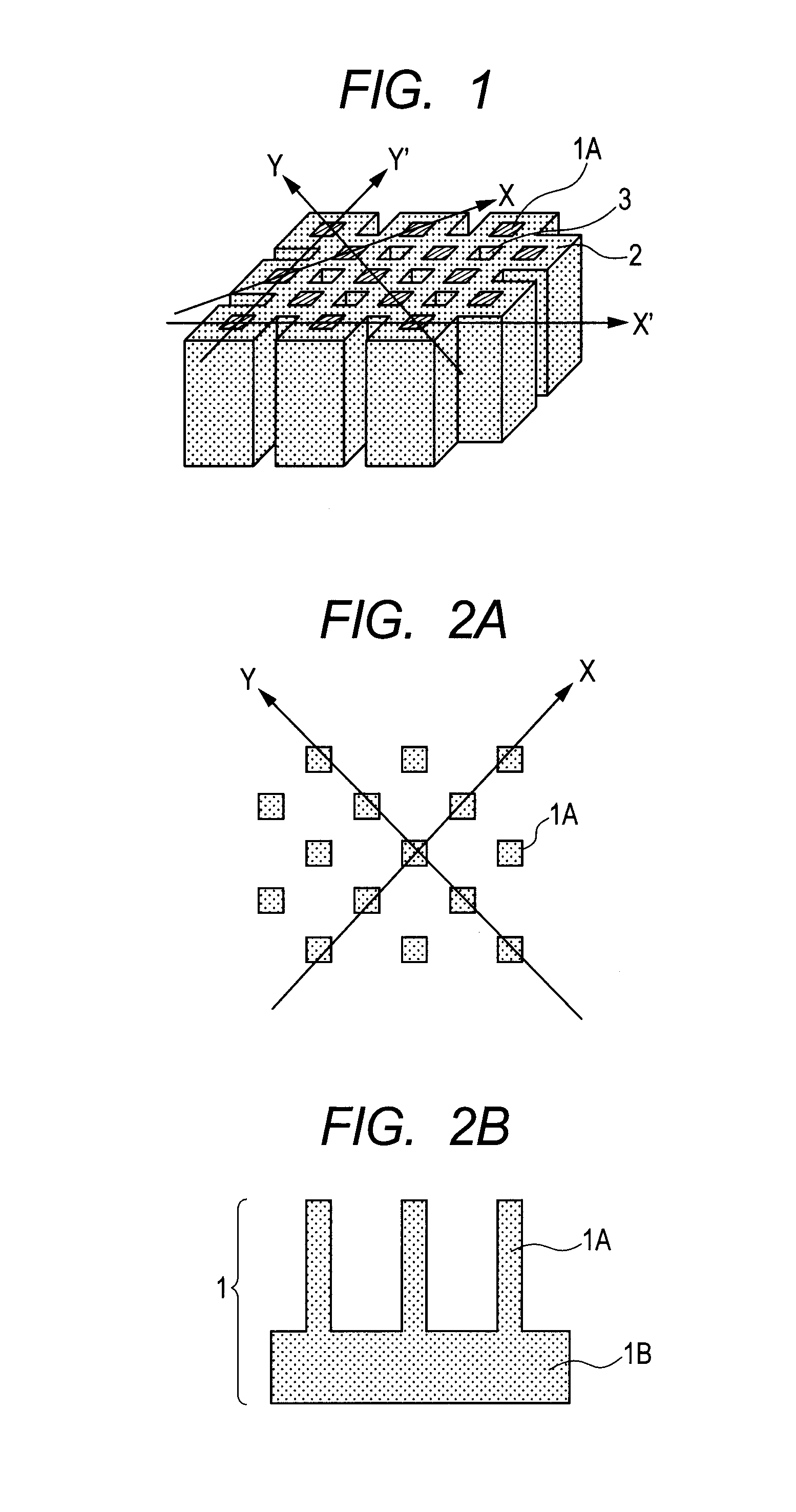
[0046]As a substrate, a Si wafer was used. A photosensitive material which was spin coated on a surface of the wafer was used to carry out desired patterning. After that, dry etching was performed to form columnar structures having an equal period in two-dimensional directions as illustrated in FIGS. 2A and 2B. Individual columnar structures which were formed were squares of 2×2 μm when cut along the plane perpendicular to long sides of the columnar structures and had a period of 5.6 μm in each of the X direction and Y direction that were orthogonal to each other. Further, the columnar structures had a height of 50 μm. After that, a Ti film was formed at a thickness of 10 nm at tips of the Si columnar structures by vapor deposition, which was followed by formation of a Au film at a thickness of 200 nm.

[0047]Gold plating was given with the obtained Ti / Au layer being as a seed ...

example 2

[0048]As Example 2, an example of manufacturing an X-ray shield grating having a period of 8 μm is described.

[0049]As a substrate, a Si wafer was used. A photosensitive material was spin coated on a surface of the wafer. Similarly to the case of Example 1, desired patterning was carried out and dry etching was performed to form columnar structures. Individual columnar structures which were formed were squares of 4×4 μm when cut along the plane perpendicular to long sides of the columnar structures and were arranged with a period of 11.3 μm in the X direction and Y direction that were orthogonal to each other. After that, in a method similar to that in Example 1, a gold layer having a thickness of 4 μm was formed by gold plating, and gold at the top of the Si columnar structures and over the supporting member was removed by dry etching using Ar. Then, the Si substrate was removed by dry etching using CF4. In this way, a gold periodic structure was obtained that could be used as the X...


PUM

PropertyMeasurementUnit
angleaaaaaaaaaa
heightaaaaaaaaaa
thicknessaaaaaaaaaa

Abstract

A two-dimensional X-ray shield grating which may be manufactured more easily and to a manufacturing method to provide therefor is provided. The method of manufacturing the X-ray shield grating includes: a first step of forming a plurality of columnar structures periodically arranged in two directions; and a second step of forming a film which surrounds at least side surfaces of the respective plurality of columnar structures, in which, in the second step, portions of the film formed on side surfaces of columnar structures which are adjacent to each other in the two directions among the plurality of columnar structures are connected to each other in the two directions, and in which the film is formed so that a columnar aperture is formed between columnar structures which are diagonally adjacent to each other with respect to the two directions among the plurality of columnar structures.

Description

BACKGROUND OF THE INVENTION[0001]1. Field of the Invention[0002]The present invention relates to an X-ray shield grating, a manufacturing method therefor, and an X-ray imaging apparatus.[0003]2. Description of the Related Art[0004]X-ray phase contrast imaging is a method of obtaining a phase image of a test object by detecting a phase shift of X rays. X-ray phase contrast imaging includes a method using Talbot interference. A method in which X-ray phase contrast imaging is performed using Talbot interference method is hereinafter referred to as an X-ray Talbot interference method.[0005]FIG. 7 illustrates an exemplary structure of an imaging apparatus using the X-ray Talbot interference method. The imaging apparatus using the X-ray Talbot interference method generally includes an X-ray source 8 for emitting spatially coherent X rays, a diffraction grating 10 for periodically modulating phase of the X rays, an X-ray shield grating 11 in which shielding portions and transmitting portio...

Claims


Application Information

Patent Timeline
Patent Type & Authority Applications(United States)
IPC IPC(8): G01N23/04G21K1/00B23P19/04
CPCG21K1/06Y10T29/49826G21K2207/005G21K2201/067
Inventor NAKAMURA, TAKASHI
Owner CANON KK
Why Eureka
Try Eureka