Three-dimensional video imaging device

a video imaging and three-dimensional technology, applied in the field of video imaging, can solve the problems of affecting the overall 3d image display effect, poor refracting effect, and reducing the overall image brightness and resolution, so as to reduce or eliminate stray lights, reduce the thickness of stacked structures, and simplify the manufacturing process

Inactive Publication Date: 2011-07-28
J TOUCH CORPORATION
View PDF3 Cites 43 Cited by
  • Summary
  • Abstract
  • Description
  • Claims
  • Application Information

AI Technical Summary

Benefits of technology

[0009]Another objective of the present invention is to provide a 3D video imaging device capable of reducing the stray lights of a 3D image.
[0010]A further objective of the present invention is to provide a 3D video imaging device that will not reduce the brightness of a 3D image.
[0016]The light-shielding elements are installed at respective gaps between each lens and another lens for reducing or eliminating stray lights.
[0017]To simplify the manufacturing process and reduce the thickness of the stacked structure, the substrate can be integrally formed with the lens array unit, or the substrate is omitted directly and the plurality of light-shielding elements are formed directly onto the light entry surface of the lens array unit by the spluttering or thin film attachment method.
[0018]The display unit is installed under the lens array unit and the substrate for displaying a multiple of images that produce the 3D image, and the multiple of images pass through the lens array unit and the light shielding elements, such that the images can be transmitted to a viewer's left and right eyes to produce the 3D image effect, and after the light shielding elements filter unnecessary stray lights of the images, the 3D image seen by the viewer will become sharper, and the overall brightness of the displayed 3D image will not be reduced.

Problems solved by technology

However, edges of the lens structure have limitations on refraction, and thus the refracting effect is poor.
If there is a manufacturing error of the lenticular lens, stray lights will be produced due to an uneven lens surface, and a portion of the 3D image may become blurred, and thus the overall 3D image display effect is affected adversely.
Compared with the lenticular lens, the barrier type provides a sharper image for a single eye, but its structural characteristic will lower the overall image brightness and resolution.
Although the structure can overcome the problem of stray lights, the manufacturing method is too complicated for a practical application.

Method used


Image

  • Three-dimensional video imaging device
  • Three-dimensional video imaging device
  • Three-dimensional video imaging device

Examples


Embodiment Construction

[0025]The technical characteristics of the present invention will become apparent with the detailed description of the preferred embodiments and the illustration of the related drawings.

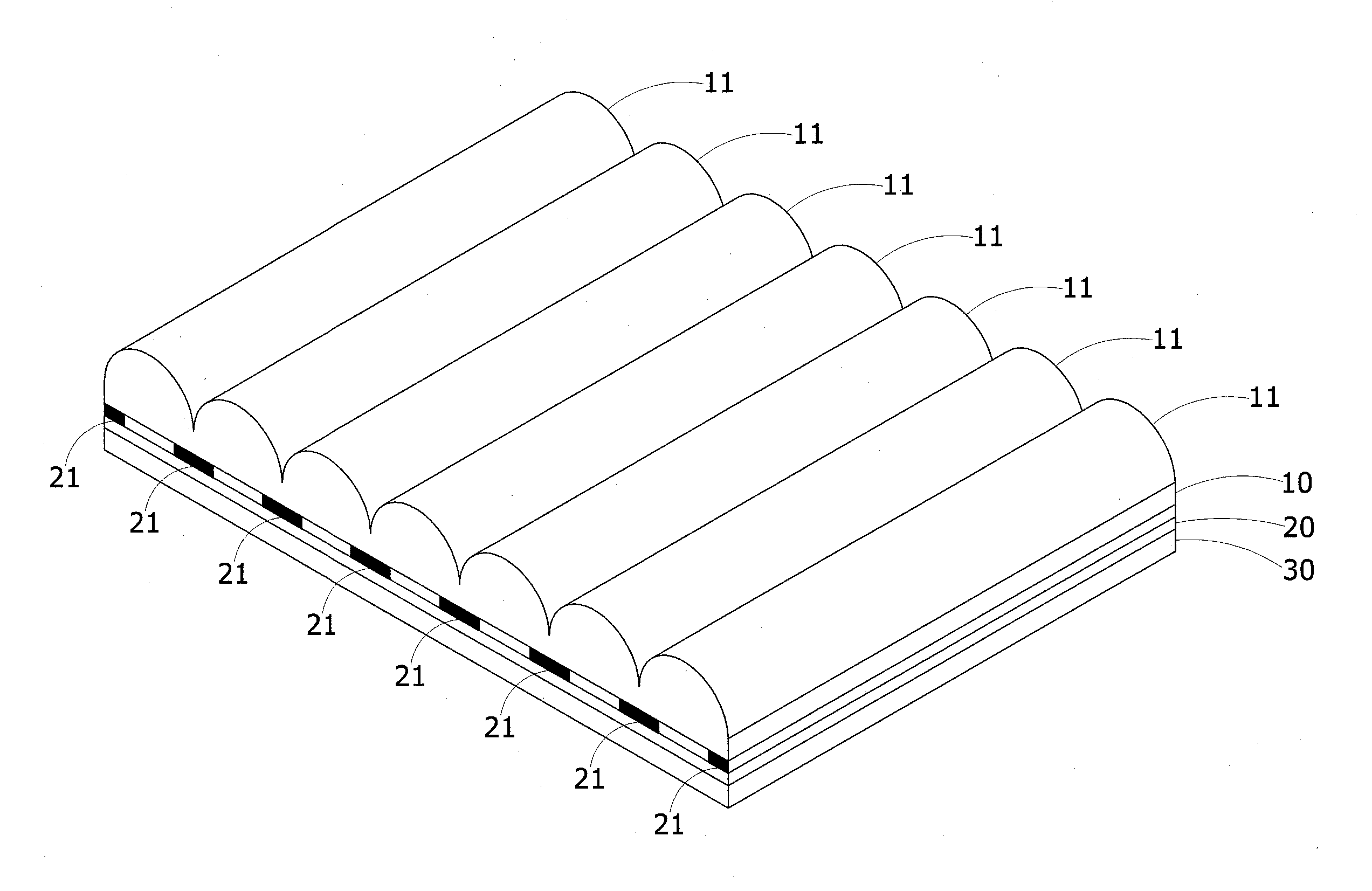
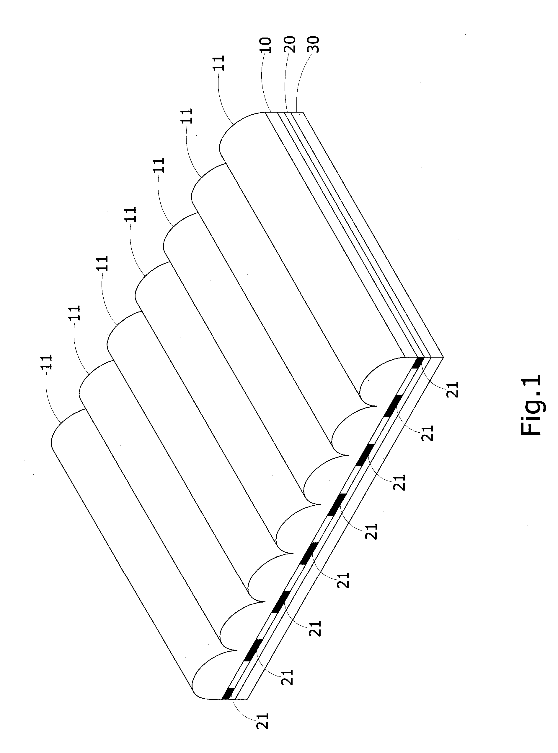
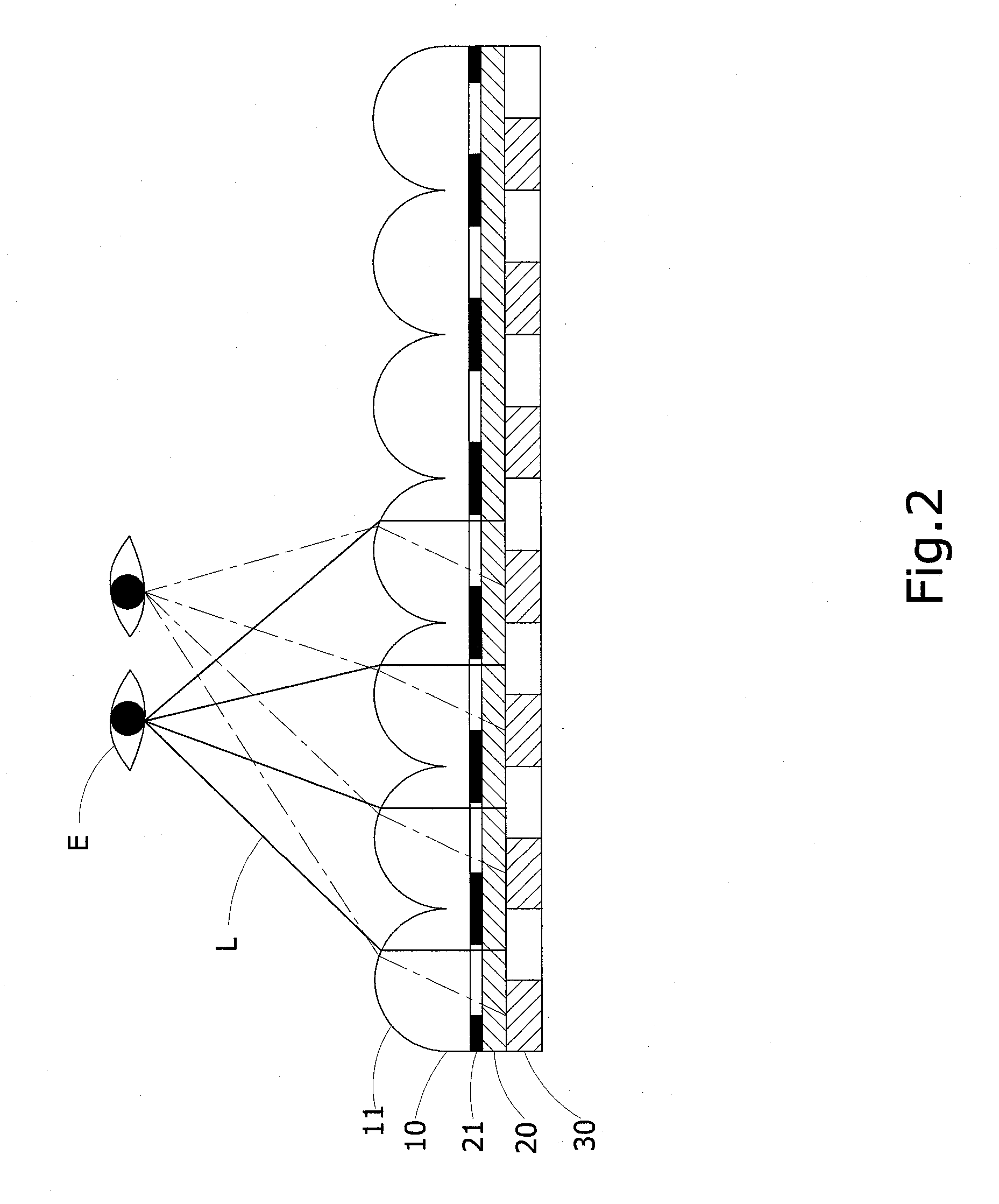
[0026]With reference to FIGS. 1 to 3 for a perspective view and a cross-sectional side view of a first preferred embodiment and a cross-sectional side view of a second preferred embodiment of the present invention respectively, a 3D video imaging device of the invention comprises a lens array unit 10, a substrate 20 and a display unit 30.

[0027]The lens array unit 10 includes a plurality of lenses 11 arranged in a horizontal direction.

[0028]The substrate 20 is disposed at a position under the lens array unit 10 and made of a transparent sheet material selected from the collection of glass, polyethylene terephthalate (PET), polycarbonate (PC), polyethylene (PE), polyvinyl chloride (PVC), polypropylene (PP), polystyrene (PS), polymethylmethacrylate (PMMA), and cycloolefin copolymer (COC).

[0029]A plurali...


PUM


Abstract

A three-dimensional (3D) video imaging device includes a lens array unit, a substrate and a display unit. The lens array unit includes a plurality of lenses, and a plurality of light-shielding elements are installed on either a top surface or a bottom surface of the substrate and arranged with an interval apart from each other and corresponding to respective gaps between the lenses. The substrate is disposed above or under the lens array unit, or the substrate is integrally formed with the lens array unit, or the substrate is omitted. The light-shielding elements are installed directly onto a light entry surface of the lens array unit to simplify the stacked structure and the manufacturing process. The 3D video imaging device can achieve the effects of preventing stray lights, enhancing 3D image sharpness, and maintaining a high-resolution display.

Description

BACKGROUND OF THE INVENTION[0001]1. Field of the Invention[0002]The present invention relates to a video imaging field, and more particularly to a three-dimensional (3D) video imaging device capable of preventing stray lights and improving 3D image sharpness.[0003]2. Description of the Related Art[0004]In present existing 3D image display technologies, binocular disparity is generally used for receiving different images by a viewer's left and right eyes, such that the viewer's brain can combine the images into a 3D image. Basically, the 3D display technologies are mainly divided into two types, respectively: a stereoscopic display and an autostereoscopic display, and the stereoscopic display includes a polarization type and a time division type, and a naked eye 3D display technology is mainly divided into a lenticular lens and a barrier according to a display structure. The aforementioned two types of display structures have both advantages and disadvantages, wherein the lenticular ...

Claims


Application Information

Patent Timeline
Patent Type & Authority Applications(United States)
IPC IPC(8): G03B35/00
CPCG03B35/22G02B5/201G02B30/27G02F1/133526
Inventor YEH, YU-CHOU
Owner J TOUCH CORPORATION
Why Eureka
Try Eureka