Wind turbine blade and wind turbine generator having the same
a technology of wind turbine generator and blade, which is applied in the installation of lighting conductors, machines/engines, transportation and packaging, etc., can solve the problems of increasing the risk of lightning strikes at other places than the blade tip and the receptor, and the rate of capture of circular receptors is not high, so as to improve the rate of lightning capture, and prevent damage to the blade body caused by lightning strikes
- Summary
- Abstract
- Description
- Claims
- Application Information
AI Technical Summary
Benefits of technology
Problems solved by technology
Method used
Image
Examples
first preferred embodiment
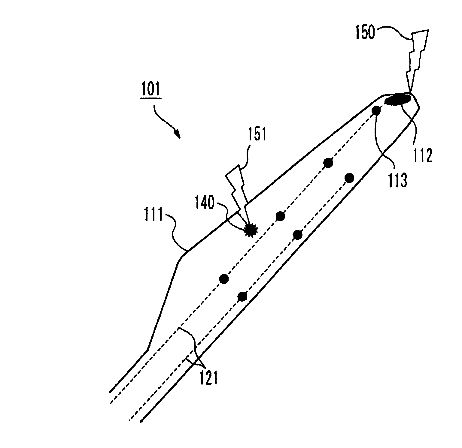
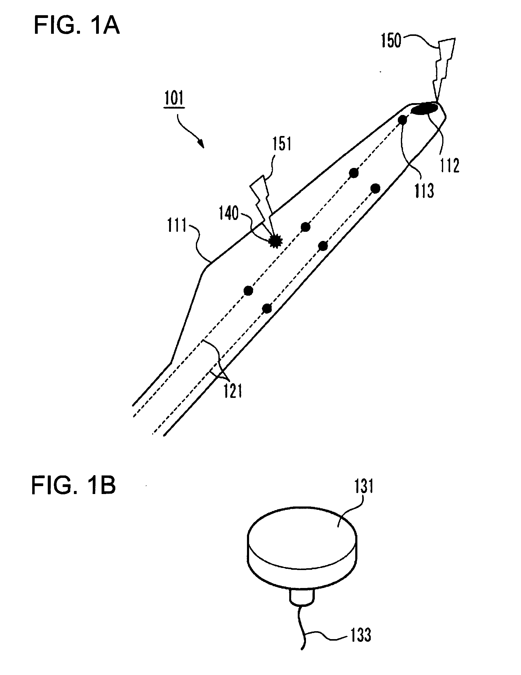
A wind turbine blade in relation to a first preferred embodiment of the present invention is described in reference to the attached drawings. The wind turbine blade of the first preferred embodiment has an external conductor layer on a surface of an outer shell. It is described in detail below.
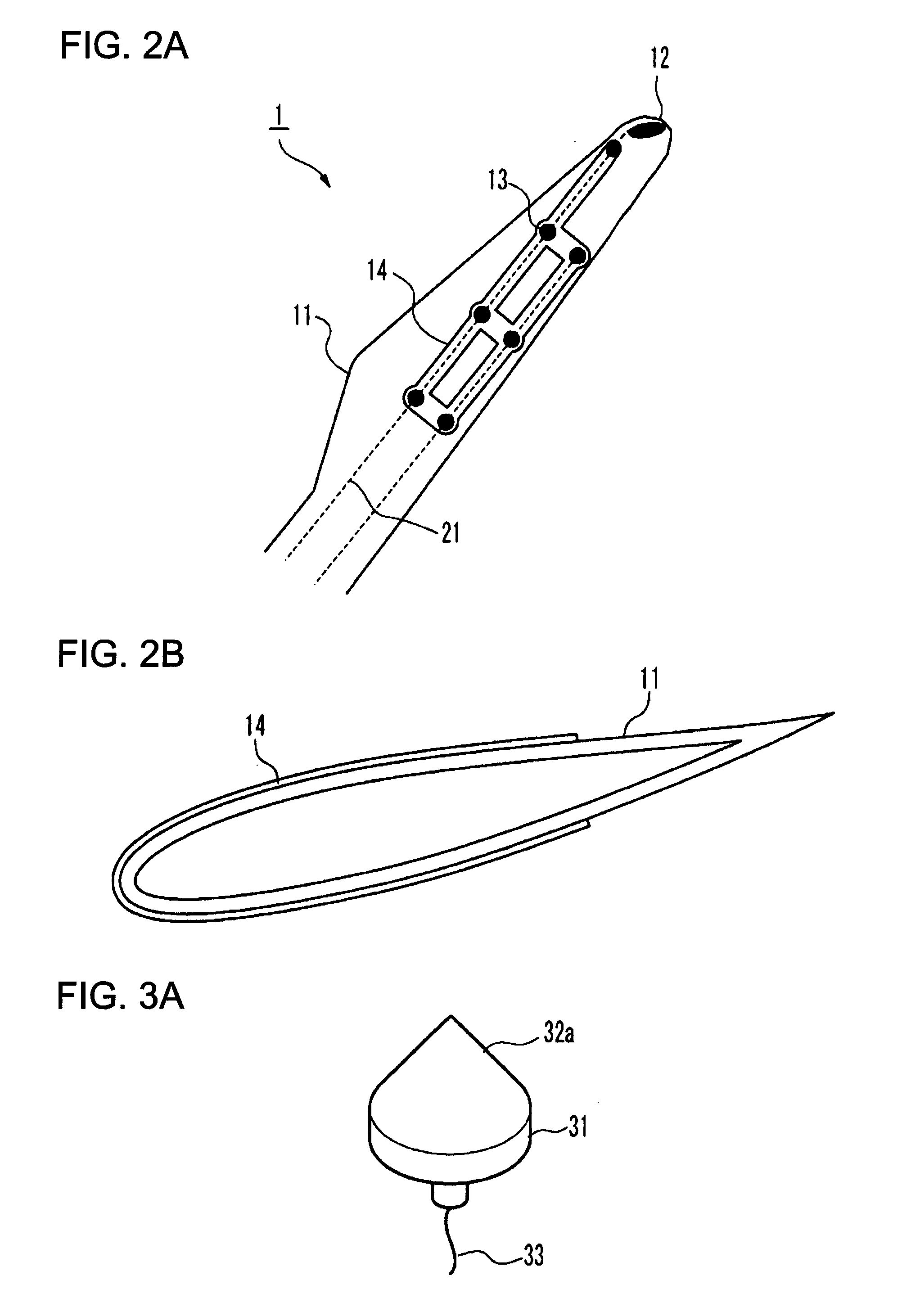
FIG. 2A is a schematic view showing a structure of a wind turbine blade in relation to the first preferred embodiment of the present invention. The wind turbine blade 1 has a blade body 11, a rod receptor 12, a plurality of disk receptors 13, a conductor layer 14 and downconductors 21. The rod receptor 12 is embedded in a tip part of the blade body 11 to be exposed on the surface of the blade body 11. The disk receptors 13 are embedded in the blade body 11 on its tip side to be exposed on the surface of the blade body 11. The external conductor layer 14 is provided in the areas around the disk receptors 13 and the rod receptor 12 on the surface of the blade body 11. The external conductor laye...
second preferred embodiment
A wind turbine blade in relation to a second preferred embodiment of the present invention is described in reference to the attached drawings. In the second preferred embodiment, the disk receptor has a convex portion (protruding object) as a lightning protection. It is explained in detail below. The structure of the wind turbine blade other than the disk receptor may be, but not limited to the one illustrated in FIG. 1A or the one explained in other preferred embodiments and is not explained further.
FIG. 3A is a schematic view showing a structure of a disk receptor in relation to the second preferred embodiment of the present invention. The disk receptor 31 has a receptor body 31, a convex portion 32a and a wire 33. The receptor body 31 is a conductive member having a shape of a disk. The top surface is formed along the surface of the blade body 11. The convex portion 32a is a conductive member, e.g. metal, having a conical shape disposed on the disk-shaped top surface. The bottom ...
third preferred embodiment
A wind turbine blade in relation to a third preferred embodiment of the present invention is described in reference to the attached drawings. In the preferred embodiment, an insulator is provided around the downconductors as a measure for lightning protection. The details are described below.
FIG. 4A is a schematic view showing a structure of a wind turbine blade in relation to a third preferred embodiment of the present invention. The wind turbine blade has a blade body 11, a rod receptor (unshown), a plurality of disk receptors (unshown), downconductors 21 and an insulating covering member 23. The downconductors 21 are connected to the disk receptors and the rod receptor and arranged across the inside of the blade body 11. The insulating covering member 23 is an insulator covering the surface of the downconductor 21. The rod receptor and the disk receptors are the same as those of the first preferred embodiment. In such a case that the wind turbine blade 1 is installed in a wind tu...
PUM
 Abstract
Description
Claims
Application Information
 - R&D
- Intellectual Property
- Life Sciences
- Materials
- Tech Scout
- Unparalleled Data Quality
- Higher Quality Content
- 60% Fewer Hallucinations
Browse by: Latest US Patents, China's latest patents, Technical Efficacy Thesaurus, Application Domain, Technology Topic, Popular Technical Reports.
© 2025 PatSnap. All rights reserved.Legal|Privacy policy|Modern Slavery Act Transparency Statement|Sitemap|About US| Contact US: help@patsnap.com


