Cooling adapter

a cooling adapter and adapter technology, applied in the direction of cylinders, mechanical equipment, machines/engines, etc., can solve the problem that the efficiency of cooling exhaust gas in the cooling adapter is likely to decrease, and the deformation by a bending moment in that region can be held small, and the effect of efficiently exchanging hea

Inactive Publication Date: 2011-08-04
TOYOTA JIDOSHA KK
View PDF3 Cites 7 Cited by
  • Summary
  • Abstract
  • Description
  • Claims
  • Application Information

AI Technical Summary

Benefits of technology

[0017]Thus, in the cooling adapter, it is also preferable that the inlet portion have a thick portion formed therearound for fixing a joint, and that the inlet portion be provided such that the thick portion is so located as to correspond to the space portion between the adjacent ones of the exhaust passages in the water jacket. In that case, the inlet portion is provided such that the thick portion formed around the inlet portion to fix the joint is so located as to correspond to the aforementioned space portion. Therefore, the geometric moment of inertia of that region of the cooling adapter which corresponds to the aforementioned space portion is large, and the amount of deformation by a bending moment in that region can be held small.
[0018]Further, it is also preferable that the inlet portion be provided on one side in a direction in which the plurality of the exhaust passages are arranged, and that the outlet portion be provided on the other side. In that case, the cooling liquid in the water jacket is likely to flow from one side to the other side in the direction in which the plurality of the exhaust passages are arranged. Therefore, the cooling liquid is less likely to flow into that region of the water jacket which is located between the adjacent ones of the exhaust passages. However, the aforementioned input portion is so provided as to open at the position corresponding to the gap between the adjacent ones of the exhaust passages. Therefore, the cooling liquid is not unlikely to flow into that region of the water jacket which is located between the adjacent ones of the exhaust passages as described above, and the efficiency of cooling exhaust gas in the cooling adapter can be restrained from decreasing as a result.
[0019]In the cooling adapter, the air that has entered the water jacket is likely to accumulate in an upper portion in the water jacket. It is preferable to swiftly discharge this air to the outside from the outlet portion, from the standpoint of efficiently exchanging heat between the cooling liquid flowing through the water jacket and the exhaust gas passing through the exhaust passages. Thus, in the cooling adapter, it is also preferable that the inlet portion be provided below the exhaust passages, and that the outlet portion be provided above the exhaust passages and so open as to connect to an uppermost portion of the water jacket.
[0020]According to the cooling adapter as described above, the cooling liquid flows into the water jacket from the inlet portion that is provided below the cooling adapter (below the exhaust passages), and the cooling liquid in the water jacket flows out from the outlet portion that is provided above the cooling adapter (above the exhaust passages) and so opens as to connect to the uppermost portion of the water jacket. Thus, even when the air accumulates in the upper portion in the water jacket as described above, it is possible to swiftly discharge the air from the outlet portion to the outside through the flow of the aforementioned cooling liquid.
[0021]Further, in the cooling adapter, it is also preferable that the outlet portion be so provided as to open to the water jacket on a more distal end side than that one of the plurality of the exhaust passages which is located at the other end in the direction in which the exhaust passages are arranged. In the case of this cooling adapter, the outlet portion is so provided as to open to the water jacket on the more distal end side than that one of the plurality of the exhaust passages which is located at the other end in the direction in which the exhaust passages are arranged, and the cooling liquid in the water jacket can be caused to flow out to the outside from the outlet portion. Accordingly, the flow of the cooling liquid to the outside can be formed in a region corresponding to the aforementioned end side in the upper portion inside the water jacket, namely, a region where air is likely to accumulate. As a result, the air can be restrained from accumulating in that region.

Problems solved by technology

By providing the cooling adapter as described above, the exhaust gas cooled by the cooling adapter can be sent to the catalyst provided in the exhaust system of the internal combustion engine, but the following problem arises inevitably.
Furthermore, as a result of the aforementioned thermal expansion in that region of the cylinder head which is located on the exhaust outlet side, the exhaust gas is likely to leak from a gap between mating faces of the cylinder head and the cooling adapter.

Method used


Image

  • Cooling adapter
  • Cooling adapter
  • Cooling adapter

Examples


Embodiment Construction

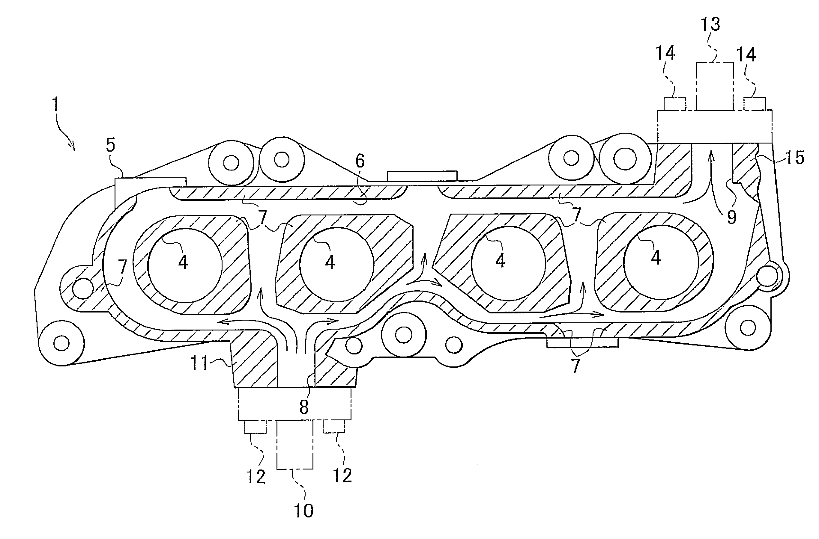
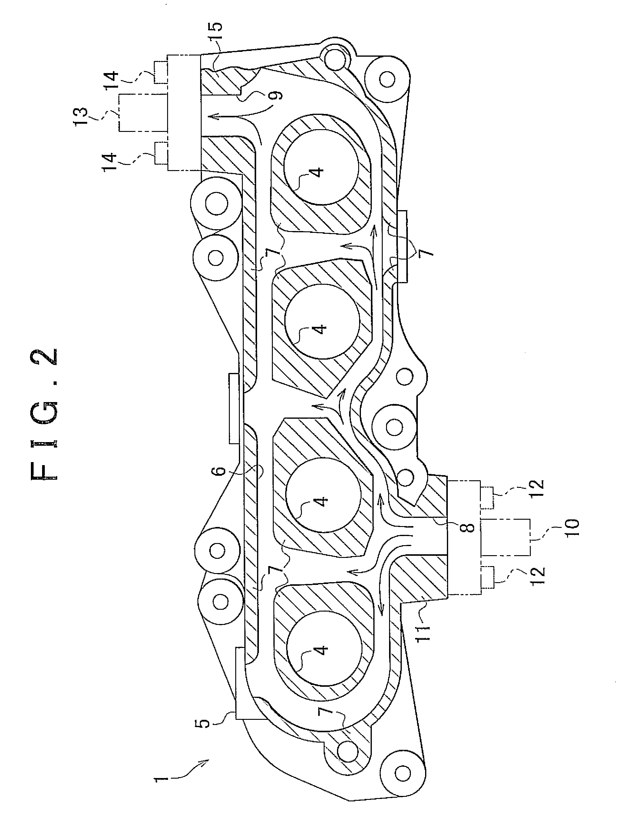
[0029]One embodiment as a concrete example of the invention will be described hereinafter with reference to FIGS. 1 to 3. As shown in FIG. 1, a cooling adapter 1 is provided between a cylinder head 2 of an internal combustion engine and an exhaust manifold 3 of the internal combustion engine in such a manner as to connect them together. This cooling adapter 1 is formed of an adapter body 5 as a single object or the like. Exhaust passages 4 for causing an exhaust gas from the cylinder head 2 of the internal combustion engine to flow to the aforementioned exhaust manifold 3 are formed through the adapter body 5. A plurality of (four in this example) of these exhaust passages 4 are provided in parallel with one another in a horizontal direction in accordance with the number of cylinders of the internal combustion engine.

[0030]In addition to the aforementioned plurality of the exhaust passages 4, a water jacket 6 for causing to flow a cooling liquid that exchanges heat with an exhaust g...


PUM


Abstract

There is provided a cooling adapter provided between a cylinder head of an internal combustion engine and an exhaust pipe of the internal combustion engine in such a manner as to connect the cylinder head and the exhaust pipe to each other. This cooling adapter is equipped with a plurality of exhaust passages provided in parallel with one another to cause an exhaust gas from the cylinder head to flow to the exhaust pipe, a water jacket formed around an entirety of the respective exhaust passages and among the respective exhaust passages to cause a cooling liquid to flow to exchange heat with the exhaust gas flowing through the plurality of the exhaust passages, an inlet portion configured to cause the cooling liquid to flow into the water jacket, and an outlet portion configured to cause the cooling liquid to flow out from inside the water jacket. The inlet portion is so provided as to open to the water jacket at a position close to the cylinder head and corresponding to a gap between adjacent ones of the exhaust passages.

Description

CROSS-REFERENCE TO RELATED APPLICATIONS[0001]This application claims priority to Japanese Patent Application No. 2010-020424 filed on Feb. 1, 2010, which is incorporated herein by reference in its entirety including the specification, drawings and abstract.BACKGROUND OF THE INVENTION[0002]1. Field of the Invention[0003]The invention relates to a cooling adapter.[0004]2. Description of the Related Art[0005]In an internal combustion engine, with a view to restraining the temperature of a catalyst provided in an exhaust system thereof from rising excessively, it is considered to cool an exhaust gas in the engine by a cooling liquid. In order to realize this cooling of the exhaust gas, as disclosed in, for example, Japanese Patent Application Publication No. 11-49096 (JP-A-11-49096), it is proposed to provide a cooling adapter for exchanging heat between the exhaust gas in the internal combustion engine and the cooling liquid between a cylinder head of the internal combustion engine and...

Claims


Application Information

Patent Timeline
Patent Type & Authority Applications(United States)
IPC IPC(8): F01N3/02
CPCF01N3/02F01P2060/16F01N3/046F02F1/243F02F1/40
Inventor KAWAMOTO, NAOYA
Owner TOYOTA JIDOSHA KK
Why Eureka
Try Eureka