
Method and device for monitoring a rotational angle sensor

a technology of rotational angle sensor and monitoring device, which is applied in the direction of measurement device, sensor output conversion, instruments, etc., can solve the problems of unsatisfactory operating state, wrong operation behaviour, and inability to direct monitor the windings of the rotary transformer in the rotor in this manner, so as to improve stability and security, and avoid the effect of controlling loop

Active Publication Date: 2011-08-04
LENZE AUTOMATION
View PDF6 Cites 10 Cited by
  • Summary
  • Abstract
  • Description
  • Claims
  • Application Information

AI Technical Summary

Benefits of technology

[0016]It is an object of the claimed invention to provide a monitoring of a rotational angle sensor in an electric machine, by means of which an adverse influence on the control loop is avoided and the stability and security are increased.

Problems solved by technology

In case that the motor controller does not receive the correct signal, this will result in a wrong behaviour during operation.
It is evident that such operating states are not desirable.
A direct monitoring of the windings of the rotary transformer in the rotor is, however, not possible in this manner.
The complete monitoring of a system that is based on the above described tracking control principle is difficult.
The same voltage amplitude, however, is also present when a wire breakage occurs in the windings of the rotary transformer of the resolver.
Therefore, errors within the resolver are not detectable.
Unfortunately, this fact and the required high amplification of the input amplifier cause an evidently asymmetric modulation of the input amplifier, thereby negatively affecting the control loop stability.
This known technique may thus not always be applied.

Method used


Image

  • Method and device for monitoring a rotational angle sensor
  • Method and device for monitoring a rotational angle sensor

Examples


Embodiment Construction

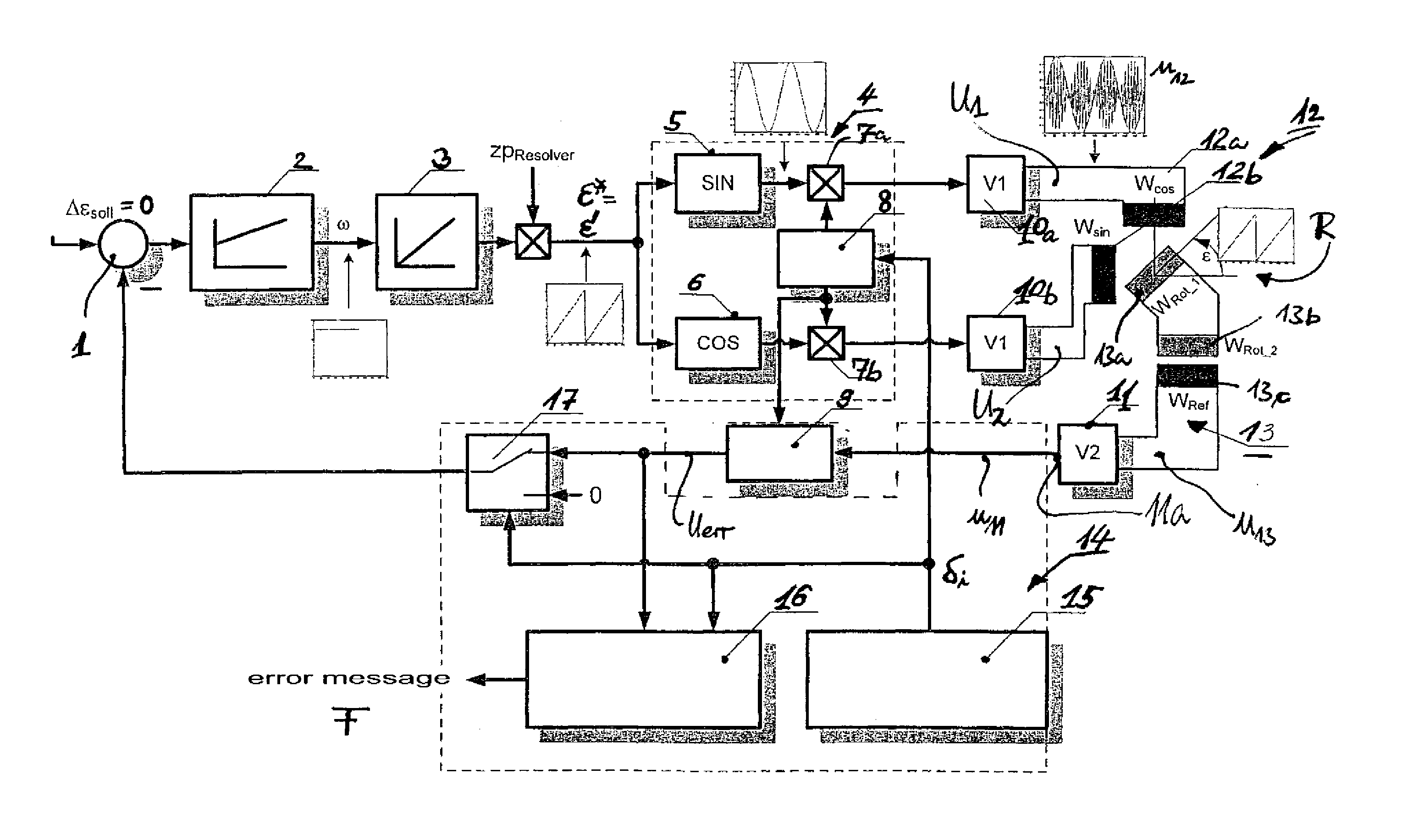
[0045]The device for monitoring a rotational angle sensor at an electric machine consists of a control difference unit 1, a controller 2 and an integrator 3 that is connected with the amplitude modulator 4.

[0046]The amplitude modulator 4 consists of a sine signal block 5 and a cosine signal block 6, as well as multipliers 7a and 7b, and a carrier frequency generator 8. The latter is connected to the (stationary) windings Wsin, Wcos (stator windings 12 as 12a and 12b) of the rotational angle sensor R.

[0047]The signal of the excitation winding WRef as a rotating winding 13 is supplied to a demodulator 9 via the input amplifier V2 (or 11).

[0048]There is provided a failure detection block 14 that consists of the interference signal generator 15, a signal analysis block 16 and a switch device as a switch 17 and that is connected to the carrier frequency generator 8 for transmitting signals δi, i=1, 2, . . . n. Likewise, the interference signal generator 15 is coupled to the switch device...


PUM


Abstract

The invention relates to a monitoring method in which two variables of angle-dependent, amplitude-modulated carrier frequency signals are emitted on orthogonal windings (12a, 12b) of the rotational angle sensor and an evaluation is carried out by an input amplifier (V2, 11) which emits an output signal that is essentially zero when the signals of the variables are gene-rated according to functional usage. Alternately, an interference signal is generated at one-second intervals in both windings (12a, 12b) of the rotational angle sensor, the result of which is being evaluated and monitored by means of an input amplifier (V2, 11). An interference display signal is generated at the output of the input amplifier (V2, 11), said interference display signal being not equal to zero if no error or interruption is present in the system and equal to zero if an error or interruption is present in the system.

Description

CROSS-REFERENCE TO RELATED APPLICATIONS[0001]The application is a U.S. National Stage Application of International Application of PCT / EP2009 / 056335 filed May 26, 2009, which claims the benefit of German Patent Application No. 10 2008 024 527.5 filed May 25, 2008, the disclosures of which are herein incorporated by reference in their entirety.FIELD OF THE DISCLOSURE[0002]The present invention relates to a method and a device for monitoring a rotational angle sensor on an electric machine and is used, for instance, in measurement systems based on a resolver.BACKGROUND[0003]For position detection of moving machine parts and drives resolvers have proven to be reliable and cost-efficient in industrial applications. If the controlling of the machine or the application requires a determination of an angle very frequently resolvers are used due to their robust construction. The resolver is an absolute position or angle measurement system that is based on an inductive principle and is in its...

Claims


Application Information

Patent Timeline
Patent Type & Authority Applications(United States)
IPC IPC(8): G01B7/30
CPCG01D5/204G01D5/2448G01D5/24461
Inventor EUTEBACH, THOMAS
Owner LENZE AUTOMATION
Learn More