Display device and FPC board fixing method thereof

Active Publication Date: 2011-08-04
NEC LCD TECH CORP
View PDF9 Cites 36 Cited by
  • Summary
  • Abstract
  • Description
  • Claims
  • Application Information

AI Technical Summary

Benefits of technology

[0047]According to another exemplary embodiment of this invention, the hole or the slit is formed in the FPC board, and wirings of the FPC board are connected to parts included in the display device. The FPC board is put in a bent state. In this state, the FPC board is fixed to the support portion by the first fixing member including the resin adhesive, the hot melt adhesive, and the pressure sensitive adhesive. Further, fixation of the FPC board in a portion in which the hole or the slit is formed is reinforced by the second fixing member including the resin adhesive, the hot melt adhesive, the pressure sensitive adhesive, and the pin inserted in the hole formed in the support portion. In this manner, rigid fixation of the FPC board may be achieved, and it is possible to prevent occurrence of a troublesome phenomenon due to a recovery force of the bent FPC board.
[0048]More specifically, the FPC board may be either an FPC board including a wiring for a liquid crystal panel (called a liquid crystal panel FPC board hereinafter) or an FPC board including a wiring for a back

Problems solved by technology

However, when the FPC board is fixed to a support portion of the liquid crystal display device in a bent state, due to a force generated in the FPC board by recovery from deformation, that is, spring-back, troublesome phenomena described below occur in some cases.
Specifically, in a liquid crystal display device including a backlight unit, a liquid crystal panel, an FPC board for backlight, which is connected to the backlight unit, and an FPC board for liquid crystal panel, which is connected to the liquid crystal panel, in a case where the FPC board for liquid crystal panel is bent to be fixed to a back surface of the backlight unit being the support portion by a double-sided pressure sensitive adhesive tape, there occurs, in some cases, a troublesome phenomenon that the FPC board for liquid crystal panel is separated f

Method used


Image

  • Display device and FPC board fixing method thereof
  • Display device and FPC board fixing method thereof
  • Display device and FPC board fixing method thereof

Examples


Example

First Exemplary Embodiment

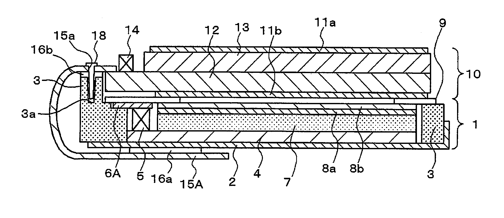
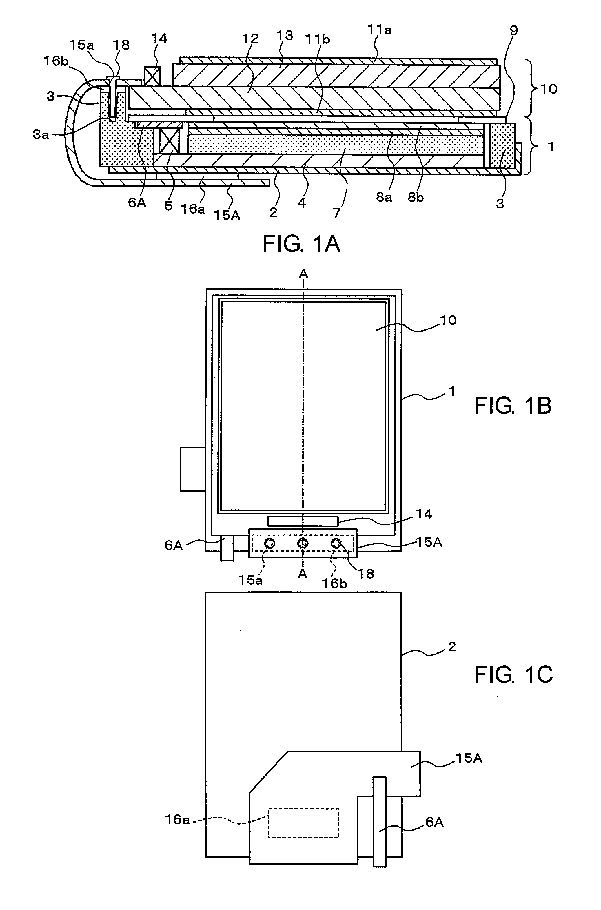
[0063]A first exemplary embodiment of this invention is described. FIG. 1A is a cross-sectional view of a liquid crystal display device according to the first exemplary embodiment. Further, FIG. 1B is a plane view seen from a front surface side (display surface side), and FIG. 1C is a plane view seen from a back surface side (rear surface side). Note that, FIG. 1A is a cross-sectional view taken along the line A-A of FIG. 1B.

[0064]A summary of the liquid crystal display device according to the first exemplary embodiment is as follows. It is to be noted that the illustrated liquid crystal display device comprises a liquid crystal panel FPC board 15A which has a wiring and electrodes for a liquid crystal panel and also has a hole or holes 15a formed therein. The liquid crystal panel FPC board 15A is adhered by double-sided pressure sensitive adhesive tapes 16a and 16b to a backlight back surface plate 2 and a frame 3, respectively, both of which act as a supp...

Example

Second Exemplary Embodiment

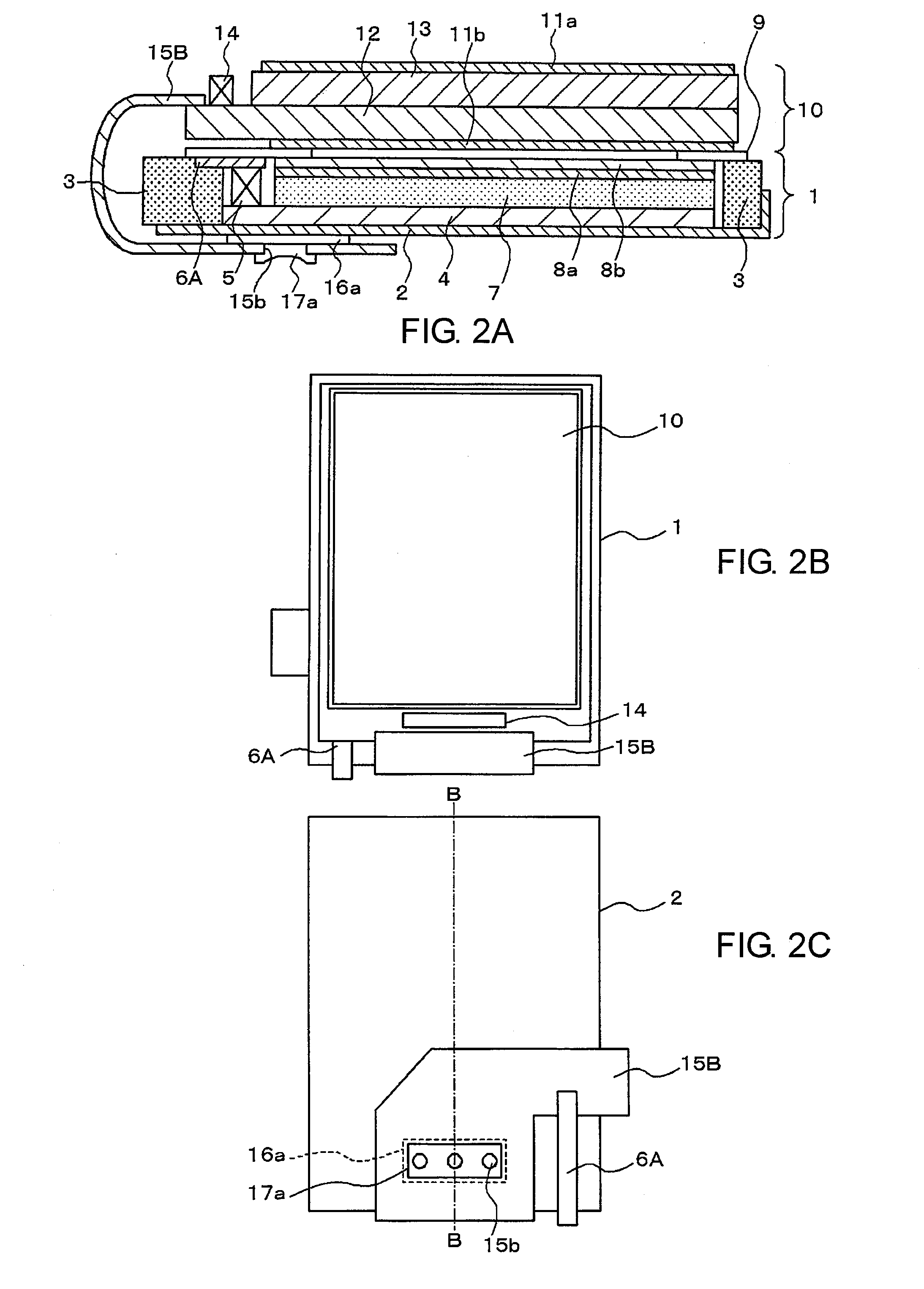
[0072]Next, a second exemplary embodiment of this invention is described. Hereinafter, similar components to those in the first exemplary embodiment are denoted by the same reference symbols, and description thereof is omitted as appropriate. FIG. 2A is a cross-sectional view of a liquid crystal display device according to the second exemplary embodiment of this invention. Further, FIG. 2B is a plane view seen from the front surface side, and FIG. 2C is a plane view seen from the back surface side. Note that, FIG. 2A is a cross-sectional view taken along the line B-B of FIG. 2C.

[0073]A summary of the liquid crystal display device according to the second exemplary embodiment is as follows. As seen in FIG. 2A, the illustrated liquid crystal display device comprises a liquid crystal panel FPC board 15B which has a wiring and electrodes for a liquid crystal panel and also has holes 15b formed therein. The liquid crystal panel FPC board 15B is adhered by the do...

Example

Third Exemplary Embodiment

[0077]Next, a third exemplary embodiment of this invention is described. FIG. 3A is a cross-sectional view of a liquid crystal display device according to the third exemplary embodiment of this invention. Further, FIG. 3B is a plane view seen from the front surface side, and FIG. 3C is a plane view seen from the back surface side. Note that, FIG. 3A is a cross-sectional view taken along the line C-C of FIG. 3B.

[0078]A summary of the liquid crystal display device according to the third exemplary embodiment is as follows. As illustrated in FIG. 3A, the liquid crystal display device comprises a liquid crystal panel FPC board for 15A which has a wiring and electrodes for liquid crystal panel and also has the holes 15a formed therein. The liquid crystal panel FPC board 15A is adhered by the double-sided pressure sensitive adhesive tape 16b to the front surface of the frame 3 which acts as a support portion. The double-sided pressure sensitive adhesive tape 16b m...


PUM

PropertyMeasurementUnit
Flexibilityaaaaaaaaaa
Sensitivityaaaaaaaaaa

Abstract

Provided is a display device capable of preventing, in a case where a flexible printed circuit board is bent to be fixed to a support portion of the display device, a troublesome phenomenon due to a force generated in the flexible printed circuit board by recovery from deformation, that is, spring-back. The display device includes the flexible printed circuit board, and the flexible printed circuit board is disposed in a bent state, and has at least a hole formed therein. The flexible printed circuit board is fixed to a support member (for example, backlight back surface plate, frame, etc.) included in the display device by a first fixation member (for example, double-sided pressure sensitive adhesive tape) and further is fixed to the support member by a second fixation member (for example, pin) through the hole.

Description

[0001]This application is based upon and claims the benefit of priority from Japanese patent application No. 2010-021081, filed on Feb. 2, 2010, the disclosure of which is incorporated herein in its entirety by reference.BACKGROUND OF THE INVENTION[0002]1. Field of the Invention This invention relates to a display device including a flexible printed circuit board and a method of fixing the flexible printed circuit board of the display device.[0003]2. Description of the Related Art[0004]In recent years, in small-sized liquid crystal display devices, there has been employed a chip on glass (COG) method in which a driver IC for driving liquid crystal is mounted on a liquid crystal panel. Here, the liquid crystal panel is connected with a flexible printed circuit board (hereinafter, referred to as FPC board) by pressure bonding through an anisotropic conductive film, and further, a backlight unit using light emitting diodes (LED) is used in most cases.[0005]As technologies related to su...

Claims


Application Information

Patent Timeline
IPC IPC(8): G02F1/13357H05K1/00G09F13/04H05K13/00
CPCG09F13/04H05K1/00Y10T29/49002H05K1/028H05K2201/10136H05K13/00G02F1/133308G02F1/13452H05K1/147H05K1/189H05K2201/09063H05K3/0061H05K3/0058G02F1/133314G02F1/133608H05K2201/10106
Inventor OOISHI, MITSUMA
Owner NEC LCD TECH CORP
Why Eureka
Try Eureka