
Motion estimation and compensation process and device

a technology of motion estimation and compensation, applied in the field of video encoding and decoding, can solve problems such as iterative process and complex structur

Inactive Publication Date: 2011-08-04
IMINDS +1
View PDF6 Cites 18 Cited by
  • Summary
  • Abstract
  • Description
  • Claims
  • Application Information

AI Technical Summary

Benefits of technology

[0017]The present invention provides a post-processing tool which can be executed entirely at the decoder side, at both encoder and decoder side, or as a separate post-processing tool not necessarily related to video coding. Compared to the prior art, the motion estimation and compensation process of the current invention substantially reduces the encoder complexity as both the estimation and compensation can take place at the decoder. The process according to the current invention has no feedback loops as a consequence of which it is not iterative. A direct advantage thereof is its increased scalability. The process also uses pixel-based motion compensation, whereas prior art refers to block-based motion compensation. An additional advantage resulting thereof is its ability to handle larger Group of Picture (GOP) lengths. A GOP is a sequence of video frames which are dependent and therefore need to be decoded together. Thanks to its pixel-based nature, the process according to the present invention does not introduce blocking artefacts, and errors do not propagate through a GOP.
[0030]Also optionally, as defined by claim 3, the matching criterion may comprise minimizing the number of bit errors on the integer number k bit planes between the block in the video frame and blocks in the reference frame.
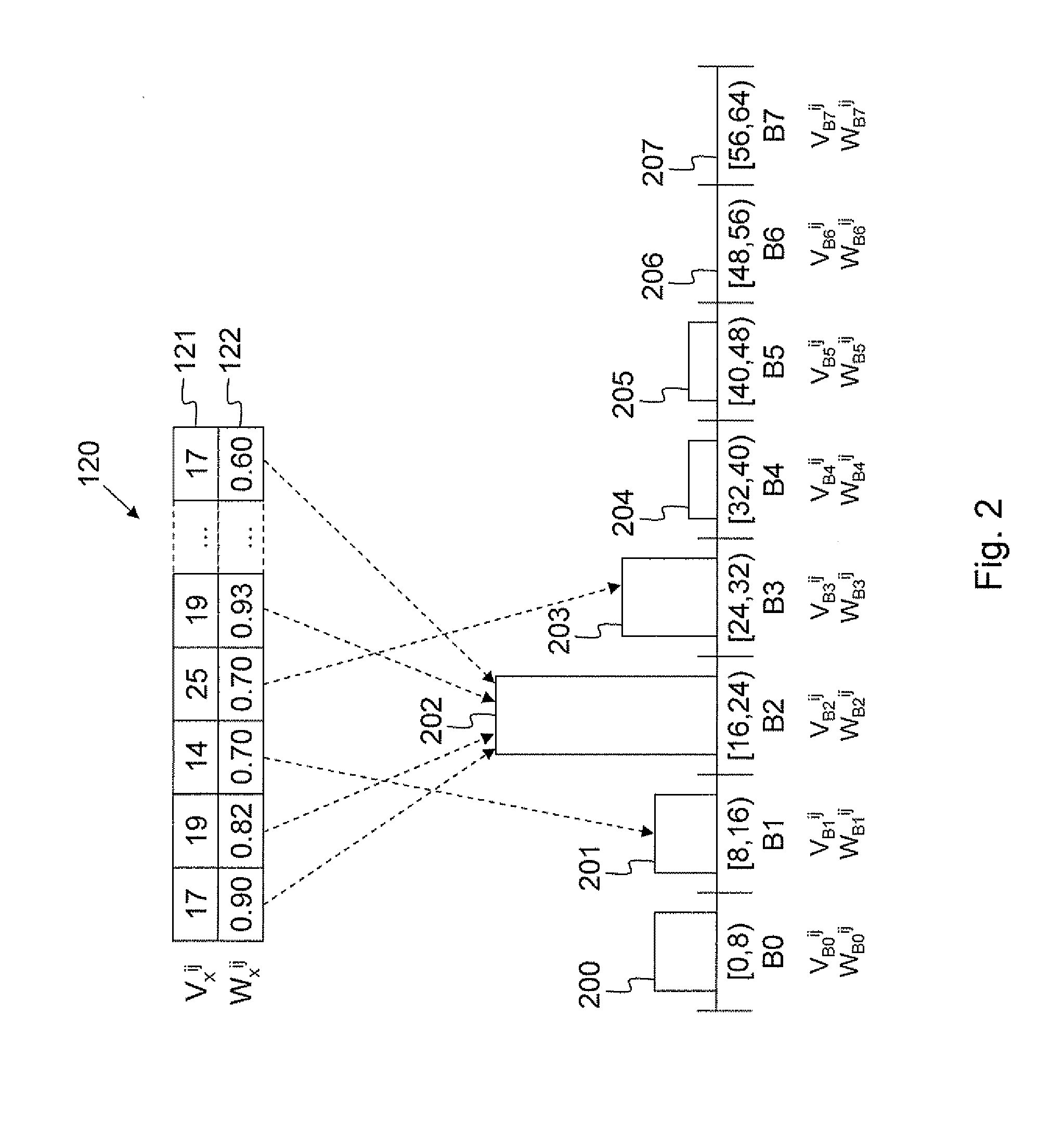
[0077]Another remark is that the motion compensation step has to use all k known bits to calculate the weight of the residual pixel value since this will minimize the uncertainty on the location of the real compensated pixel.
[0094]A first specific application is “Scalable Distributed Video Coding (SDVC)”. This technology was originally designed with Distributed Video Coding (DVC) as an application in mind. DVC requires the motion estimation process to be applied at the decoder side. Based on the reception of a number of bit planes (or a part of these bit planes) of the luminance component and of some intra-coded frames, the method according to the present invention reconstructs an approximation of the missing bit planes of the luminance and chrominance components. Using the current invention has the advantage over other DVC techniques of supporting large Group of Picture (GOP) lengths as well as supporting good compression efficiency. In addition, using the current invention does not require any feedback between encoder and decoder. This reduces the inherent communication delays produced by the use of a feedback channel in current DVC systems. When the intra-coding part is performed by a scalable video coding system, the result is a fully scalable video coding system with additional opportunities for migration of the complexity to the decoder or to an intermediate node.

Problems solved by technology

The proposed motion estimation process requires involvement of the encoder and decoder, and it is a complex, iterative process.

Method used


Image

  • Motion estimation and compensation process and device
  • Motion estimation and compensation process and device
  • Motion estimation and compensation process and device

Examples


Embodiment Construction

)

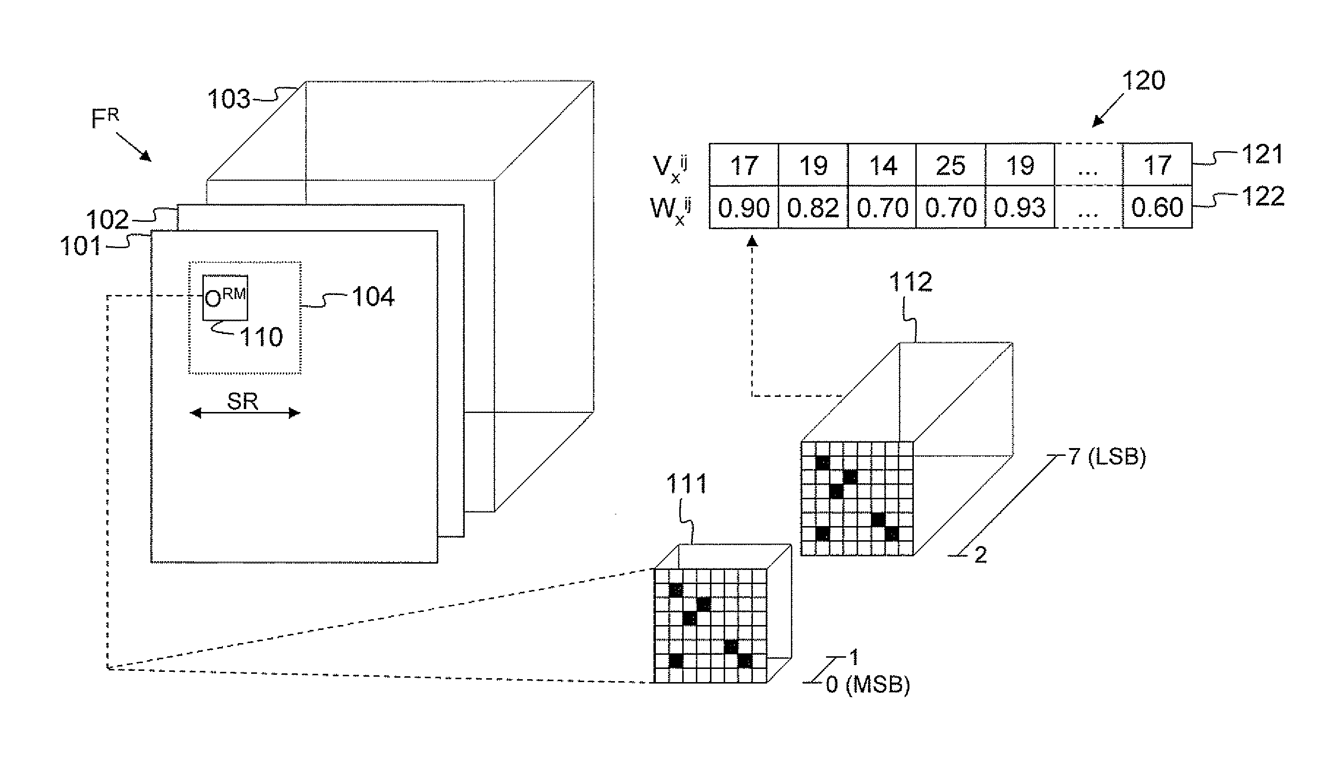
[0104]FIG. 1 illustrates motion estimation in a Wyner-Zyv decoder that is decoding a current Wyner-Zyv video frame F, not drawn in the figure. Once the first k bit planes of the current Wyner-Zyv frame F have been decoded, the motion estimation and compensation process according to the present invention is applied for the luminance data. In FIG. 1, k is assumed to equal 2 whereas the total number of bit planes that represent the luminance data is assumed to be 8. Thus, as a result of the motion estimation and compensation process, the values for the residual 6 bit planes of the luminance data will be predicted without having to encode, transmit and decode these bit planes. The chrominance data are assumed to follow the weights and prediction locations from the luminance component, but on all bit planes instead of on a subset of residual bit planes. In other words, if it is assumed that the chrominance component of the pixels is also represented by 8 bit planes, the values of these ...


PUM


Abstract

In the motion estimation and compensation process for video frames, blocks O of pixels are considered. A number k of bit planes in a block O in a video frame F are compared with blocks OR in reference frames (FR). The best matching block (ORM) is determined in the reference frames (FR). Subsequently, a weight value (Wxij) is calculated for the best matching block (ORM) based on the ratio of valid pixels therein. The residual pixel values (Vxij) extracted from the best matching block (ORM) and corresponding weight values (Wxij) are stored in a pixel prediction array (120). The pixel array is used for motion compensation of at least the luminance component of valid pixels. Invalid pixels are reconstructed from surrounding pixel values.

Description

FIELD OF THE INVENTION[0001]The present invention generally relates to video encoding and decoding, more particularly to motion estimation and compensation. Encoding / decoding digital video typically exploits the temporal redundancy between successive images: consecutive images have similar content because they are usually the result of relatively slow camera movements combined with the movement of some objects in the observed scene. The process of quantifying the motion or movement of a block of pixels in a video frame is called motion estimation. The process of predicting pixels in a frame by translating—according to the estimated motion—sets of pixels (e.g. blocks) originating from a set of reference pictures is called motion compensation.BACKGROUND OF THE INVENTION[0002]In IEEE Transactions on Image Processing, Vol. 3, No. 5 of September 1994, the authors Michael T. Orchard and Gary J. Sullivan have described a motion compensation theory based on overlapped blocks in their articl...

Claims


Application Information

Patent Timeline
IPC IPC(8): H04N7/32
CPCH04N19/51H04N19/117H04N19/583H04N19/182H04N19/184H04N19/137
Inventor CLERCKX, TOMMUNTEANU, ADRIAN
Owner IMINDS
Learn More