Smart Vibration Absorber For Traffic Signal Supports

a traffic signal and vibration absorber technology, applied in the direction of shock absorbers, machine supports, mechanical equipment, etc., can solve the problems of low fundamental natural frequency at which the signal structure will resonate, the cantilevered traffic signal support structure is particularly susceptible to wind induced vibration, and the vertical displacemen

Inactive Publication Date: 2011-08-11
UNIV OF CONNECTICUT
View PDF36 Cites 34 Cited by
  • Summary
  • Abstract
  • Description
  • Claims
  • Application Information

AI Technical Summary

Benefits of technology

[0021]Also disclosed herein are advantageous aspects and implementation of the disclosed damper component. In some exemplary embodiments, the damper may be a controllable damper, such as a magneto-rheological fluid damper interconnected with a computing device, and may include one or more strain and force sensors. The damper may be capable of receiving control signals from a computing device / processor in response to strain and force sensor readings for altering the characteristics of the damper.

Problems solved by technology

This flexibility results in a low fundamental natural frequency at which the signal structure will resonate with large amplitude vibration.
Cantilevered traffic signal support structures are particularly susceptible to wind induced vibration.
Importantly, in the case of horizontal mast arms this would result in vertical displacement.
Wind-induced galloping, most likely the primary cause of excessive vibrations in traffic signal support structures, is due to aerodynamic forces generated on nonsymmetrical cross sections, such as traffic signal structures with attachments (e.g., signs, traffic signals) to the mast arm.
As the wind velocity increases beyond the critical speed, the signal structures exhibit the galloping phenomenon which can lead to excessive and sustained vertical (in-plane) vibrations at the natural frequency (resonance) of the structure, leading to the fatigue failure thereof in a relatively short period of time.
Excessive and sustained vibration can result in damage, including fatigue damage, and live load stresses, which can significantly reduce the fatigue life of signal support structures.
However, the fatigue life of a signal support structure can be significantly increased by reducing the duration and amplitude of the vibration, thus reducing the effective stress range (i.e., the difference between the maximum and minimum stress) In a survey by the National Cooperative Highway Research Program (NCHRP) thirty states reported excessive vibrations or fatigue cracking of sign, signal, or light support structures [see Dexter R. J and Ricker M. J. NCHRP REPORT 469 Fatigue-Resistant Design of Cantilevered Signal, Sign, and Light Supports.
Fatigue cracking has often been identified as the cause of failure of in-service signal support structures.
In addition to fatigue, large deflections in traffic signal support structures can also result in serviceability issues related to the motorists' awareness of the excessive vibrations and motorist complaints.
Signal support structures adequately designed to resist fatigue loading may experience excessive vertical vibration of the mast arm.
However, this approach is not practical for many transportation structures.
This results in larger poles and mast arms, as well as overbuilt connection details.
Importantly, this approach requires replacement of the entire traffic signal support structure, with a significantly more expensive new oversized structure.
However, this type of damper is relatively complex and is expensive to manufacture.
Alternatively, a friction damper increased the damping ratio of the structure to 6.5%, however, it is considered unattractive.
However, the traditional tuned mass damper system is not practical because, with limited added mass and subsequent effectiveness, it has to be specifically designed for each specific traffic signal support structure to achieve the desired level of performance and a simple tuned mass damper design procedure has not been identified for signal support structures.
This is a major drawback of the prior technology because one design for a vibration absorber can not be applied to numerous types / sizes of traffic signal supports.
Thus it has not been possible to limit or specifically identify the number of different types of vibration absorbing equipment needed to service the wide range of traffic signal supports currently in use in the transportation infrastructure of the United States and other developed countries.

Method used


Image

  • Smart Vibration Absorber For Traffic Signal Supports
  • Smart Vibration Absorber For Traffic Signal Supports
  • Smart Vibration Absorber For Traffic Signal Supports

Examples


Embodiment Construction

)

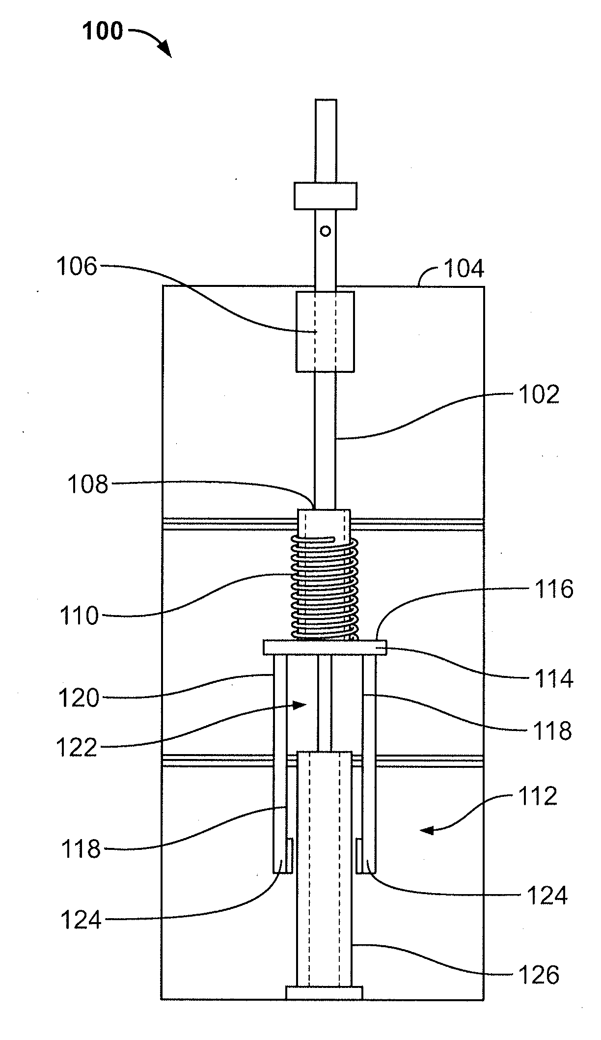
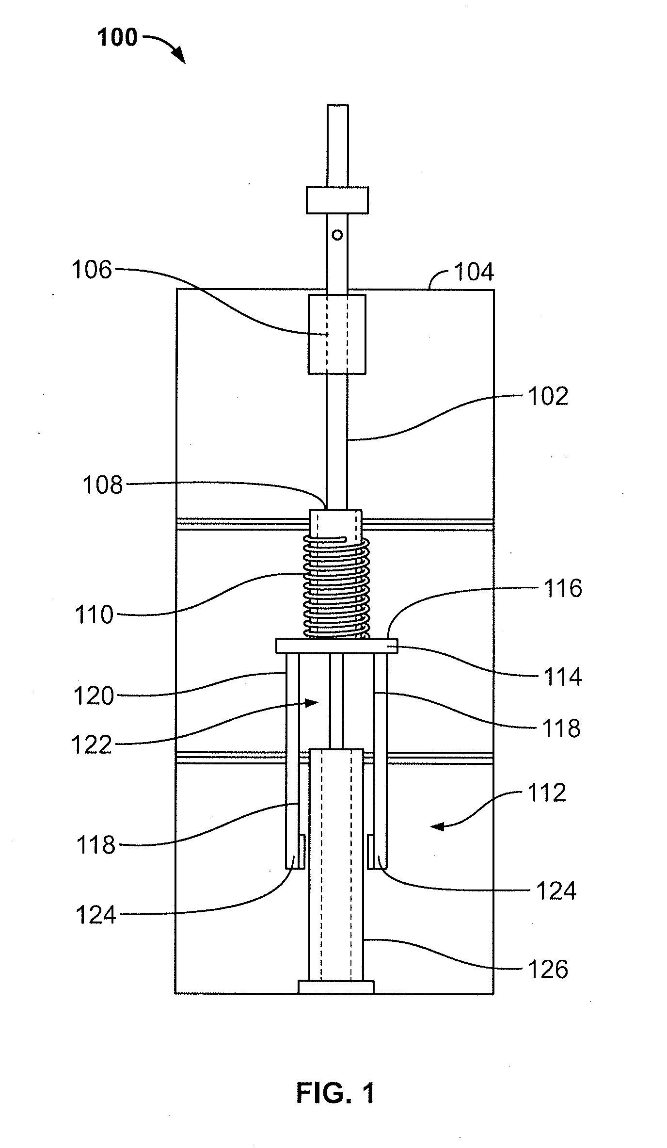
[0032]In one embodiment, the present invention is directed to a low-cost vibration mitigation device to reduce fatigue in typical cantilevered traffic signal support structures. Exemplary implementations of the disclosed invention incorporate the concept of a damped vibration absorber to reduce in-plane vibration. In the present invention, the signal heads themselves are modified so that they are no longer rigidly connected to the mast arm but, rather, are allowed to translate vertically relative to the mast arm during mast arm vibration. The signal head mass / member generally functions as a supplemental mass to absorb energy due to wind excitation. The disclosed signal head vibration absorber (SHVA) provides a relatively large supplemental mass to reduce vibration while effectively adding virtually no additional mass to the overall system. The disclosed SHVA thus provides for increased performance and improved robustness when applied to various traffic signal support structures and...


PUM


Abstract

Disclosed herein is a smart vibration absorber for traffic signal supports. In exemplary embodiments, the vibration absorber utilizes the mass of the signal head as a damped vibration absorber. The system may also include a spring and damper in mechanical communication with the signal head. The spring provides resistance to the compression force of the signal head while the damper provides a damping force removing energy from the system. Also disclosed herein is a controllable damper which may be connected to a computing device for varying the damping of the system. The controllable damper may be a magneto-rheological fluid damper. The smart vibration absorber may be constructed as a retrofit for installation on current traffic signals supports.

Description

CROSS-REFERENCE TO RELATED APPLICATION[0001]The present application claims the benefit of a co-pending provisional patent application entitled “Smart Vibration Absorber for Traffic Signal Supports,” which was filed on Jan. 8, 2010, and assigned Ser. No. 61 / 335,571. The entire contents of the foregoing provisional patent application are incorporated herein by reference.FIELD OF THE INVENTION[0002]The present invention relates generally to a vibration absorption system for minimizing the impact of vibrations on engineered support structures, and, more specifically, to a vibration absorption system that incorporates the mass of support structure attachments as part of the auxiliary mass of the vibration absorber.BACKGROUND OF THE INVENTION[0003]Traffic signals are used extensively around the United States to control conflicting flows of traffic at road intersections, crosswalks and other locations. To ensure clear visibility, these traffic signals are typically supported over the trave...

Claims


Application Information

Patent Timeline
Patent Type & Authority Applications(United States)
IPC IPC(8): F16F13/00F16F15/03
CPCF16F7/1028F16F7/1005
Inventor CHRISTENSON, RICHARD
Owner UNIV OF CONNECTICUT
Why Eureka
Try Eureka