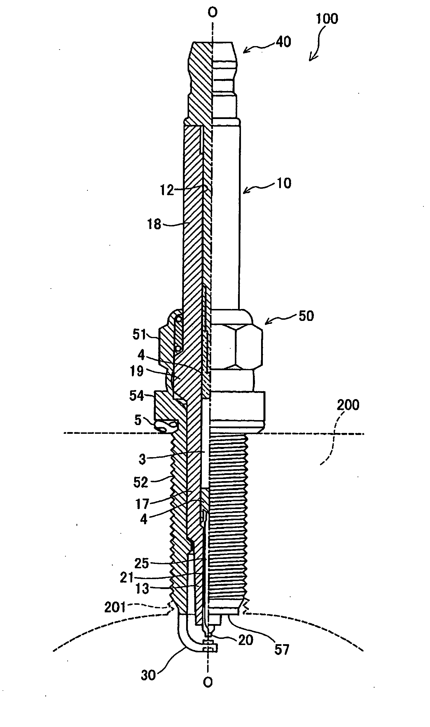
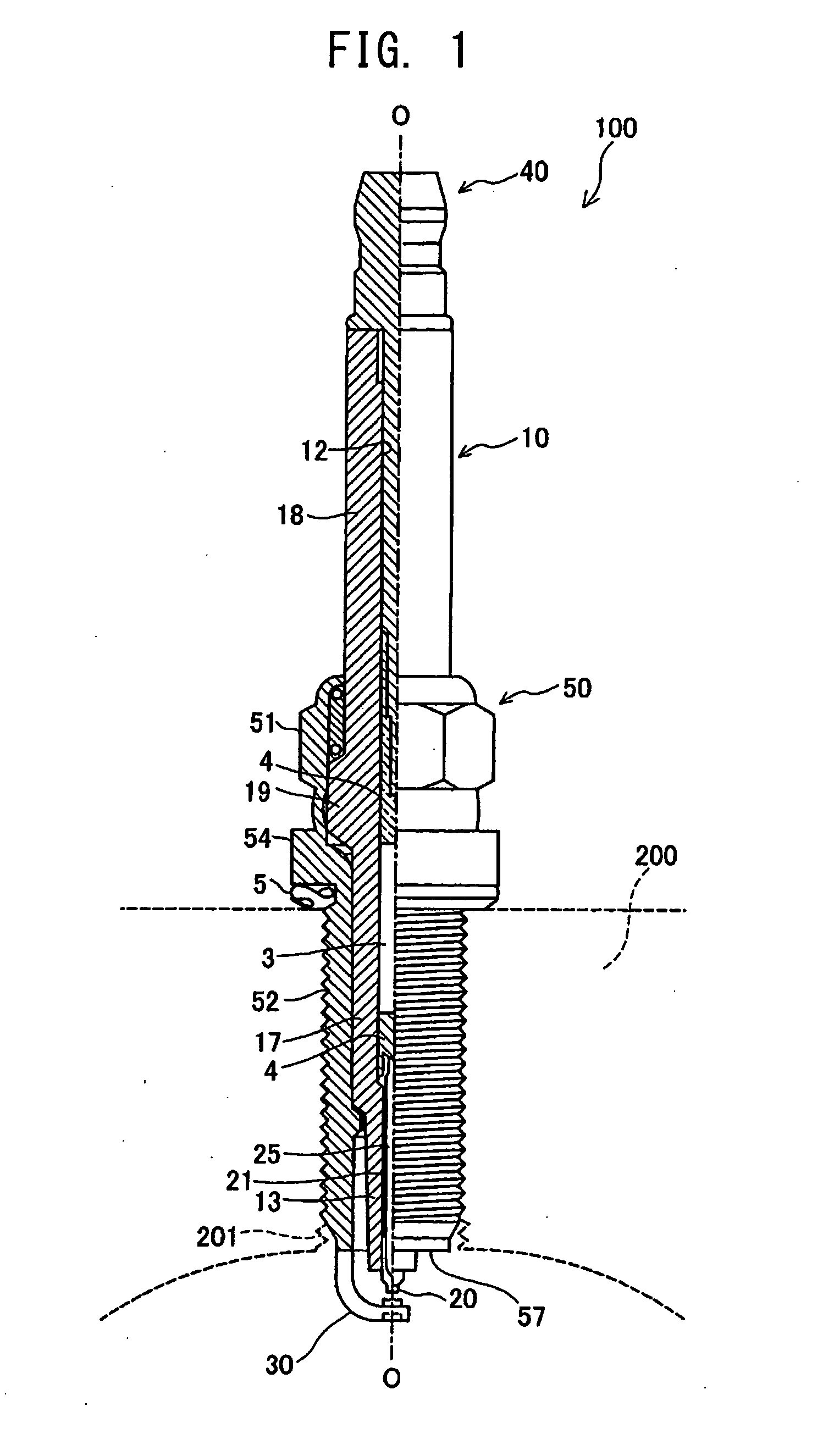
Spark plug and method of manufacturing the same
a technology of spark plugs and spark plugs, which is applied in the manufacture of spark plugs, spark plugs, electrical equipment, etc., can solve the problems of deterioration of deformation of ground electrodes that may exceed plastic regions, and insufficient degree of consideration of formation of projecting portions on ground electrodes through press work, so as to achieve stable ignition performance and improve durability of ground electrodes.
- Summary
- Abstract
- Description
- Claims
- Application Information
AI Technical Summary
Benefits of technology
Problems solved by technology
Method used
Image
Examples
application example 2
[0009]In the spark plug according to the application example 1, a relation 0.83≦C / D≦1.60 may be satisfied, where C represents an area of a boundary plane, which is a surface selected from surfaces parallel to a bottom surface of the press-formed recess portion and surrounded by the side surface of the press-formed recess portion, the selected surface containing the boundary between the first portion and the second portion to the greatest extent; and D represents an area of the bottom surface of the press-formed recess portion.
[0010]According to the spark plug of the application example 2, biting of the working pin against the ground electrode can be mitigated, and, at the same time, the projecting portion can be formed into a desired target shape.
application example 3
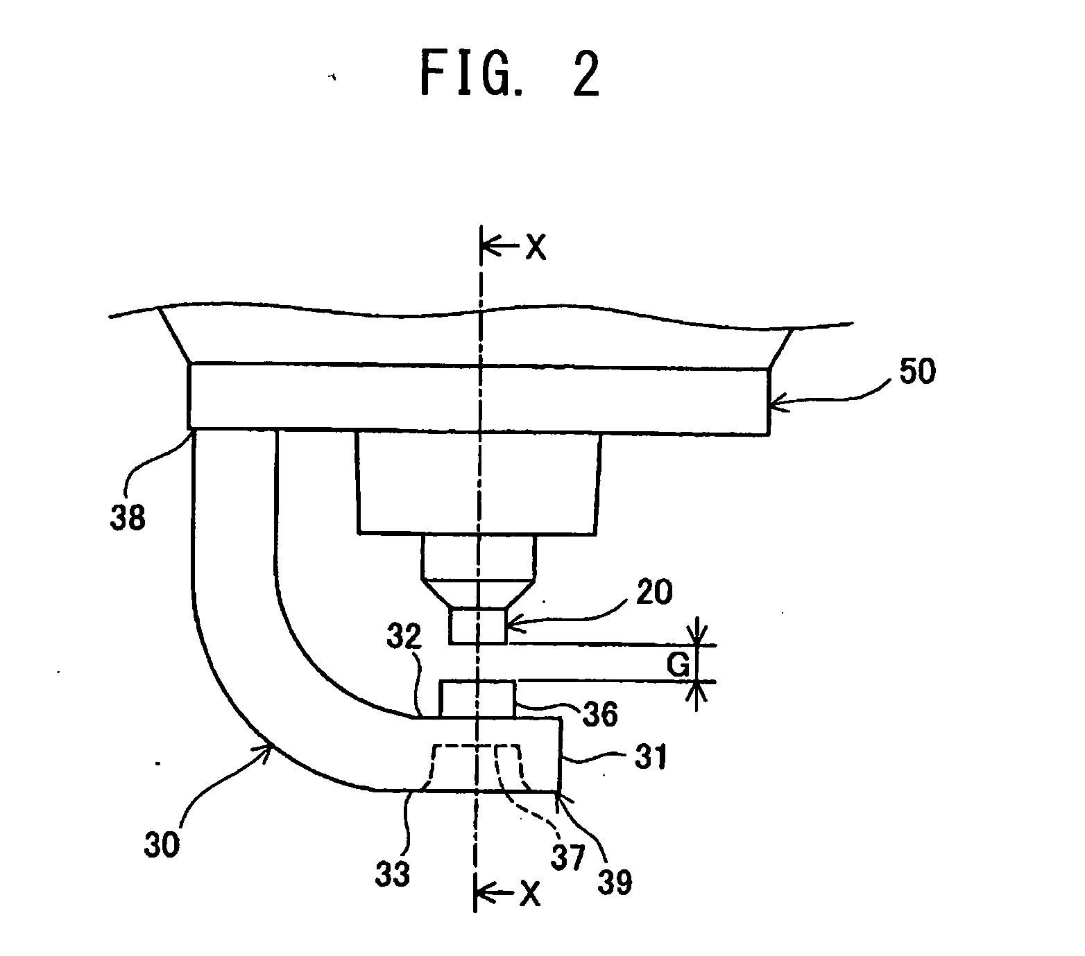
[0011]In the spark plug according to the application example 1 or 2, the ground electrode has, at its one end, a joint portion joined to the metallic shell, and, at its other end, a distal end portion having a distal end surface; the distal end surface is approximately parallel to an axial direction of the center electrode; and, as viewed on a cross section of the ground electrode parallel to the axial direction of the center electrode, passing through the centroid of the projecting portion, and perpendicular to the distal end surface, an angle E which satisfies a relation 0°≦E≦5° may be formed between a straight line E1 and a straight line E2, the straight line E1 passing through a distal end portion of the ground electrode on the side facing the center electrode and a distal-end-side root portion of the ground electrode, which is a portion of a root of the projecting portion located on the side toward the distal end of the ground electrode, and the straight line E2 passing through...
application example 4
[0013]In the spark plug according to any of the application examples 1 to 3, a ratio F1 / F2 may satisfy a relation 0.4≦F1 / F2≦1, where F1 represents a length of a flat surface extending from the root of the projecting portion to a side end of the ground electrode, and F2 represents a distance between the root and the side end of the ground electrode.
[0014]According to the spark plug of the application example 4, through suppression of deformation around the projecting portion, generation of crack, in particular, in the projecting portion or its surrounding area can be suppressed. As a result, durability of the ground electrode can be improved.
PUM
 Abstract
Description
Claims
Application Information
 - R&D
- Intellectual Property
- Life Sciences
- Materials
- Tech Scout
- Unparalleled Data Quality
- Higher Quality Content
- 60% Fewer Hallucinations
Browse by: Latest US Patents, China's latest patents, Technical Efficacy Thesaurus, Application Domain, Technology Topic, Popular Technical Reports.
© 2025 PatSnap. All rights reserved.Legal|Privacy policy|Modern Slavery Act Transparency Statement|Sitemap|About US| Contact US: help@patsnap.com


