Sheathed, annular metal nuclear fuel

Active Publication Date: 2011-08-11
ADVANCED REACTOR CONCEPTS
View PDF49 Cites 26 Cited by
  • Summary
  • Abstract
  • Description
  • Claims
  • Application Information

AI Technical Summary

Problems solved by technology

Increased energy supply from other sources, such as contribution from natural gas powered generation may be constrained by high and volatile gas prices, greenhouse gas emissions, and concerns over longer-term dependence on unstable sources of supply.
They do not, however, scale sufficiently and cannot provide enough additional electri

Method used


Image

  • Sheathed, annular metal nuclear fuel
  • Sheathed, annular metal nuclear fuel
  • Sheathed, annular metal nuclear fuel

Examples


Embodiment Construction

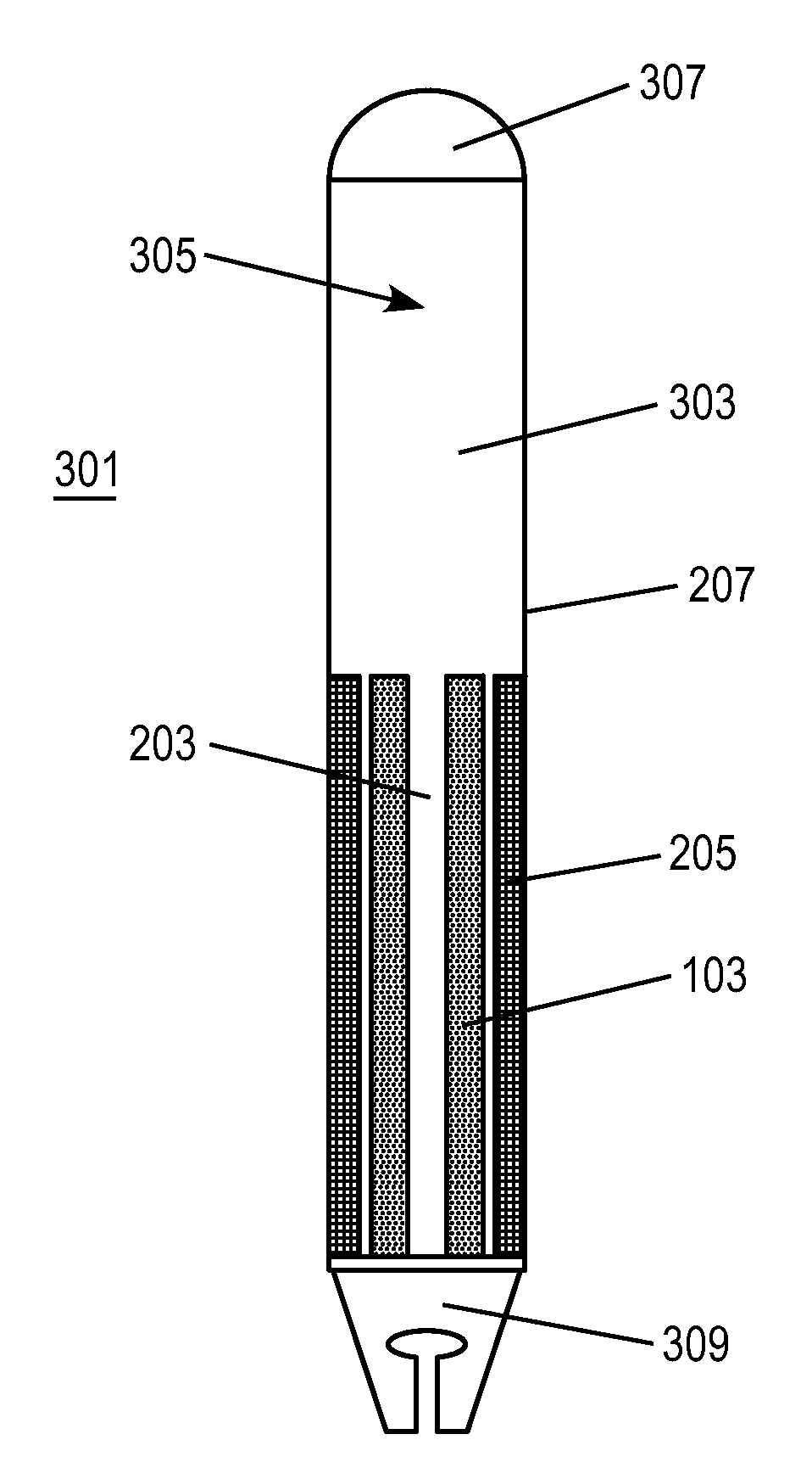
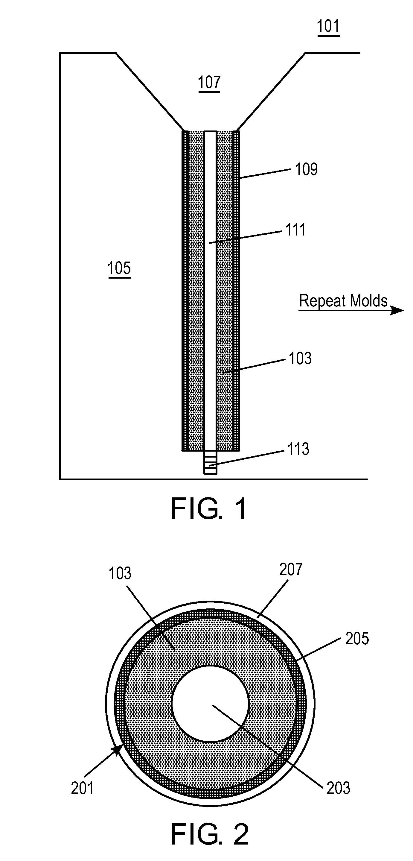
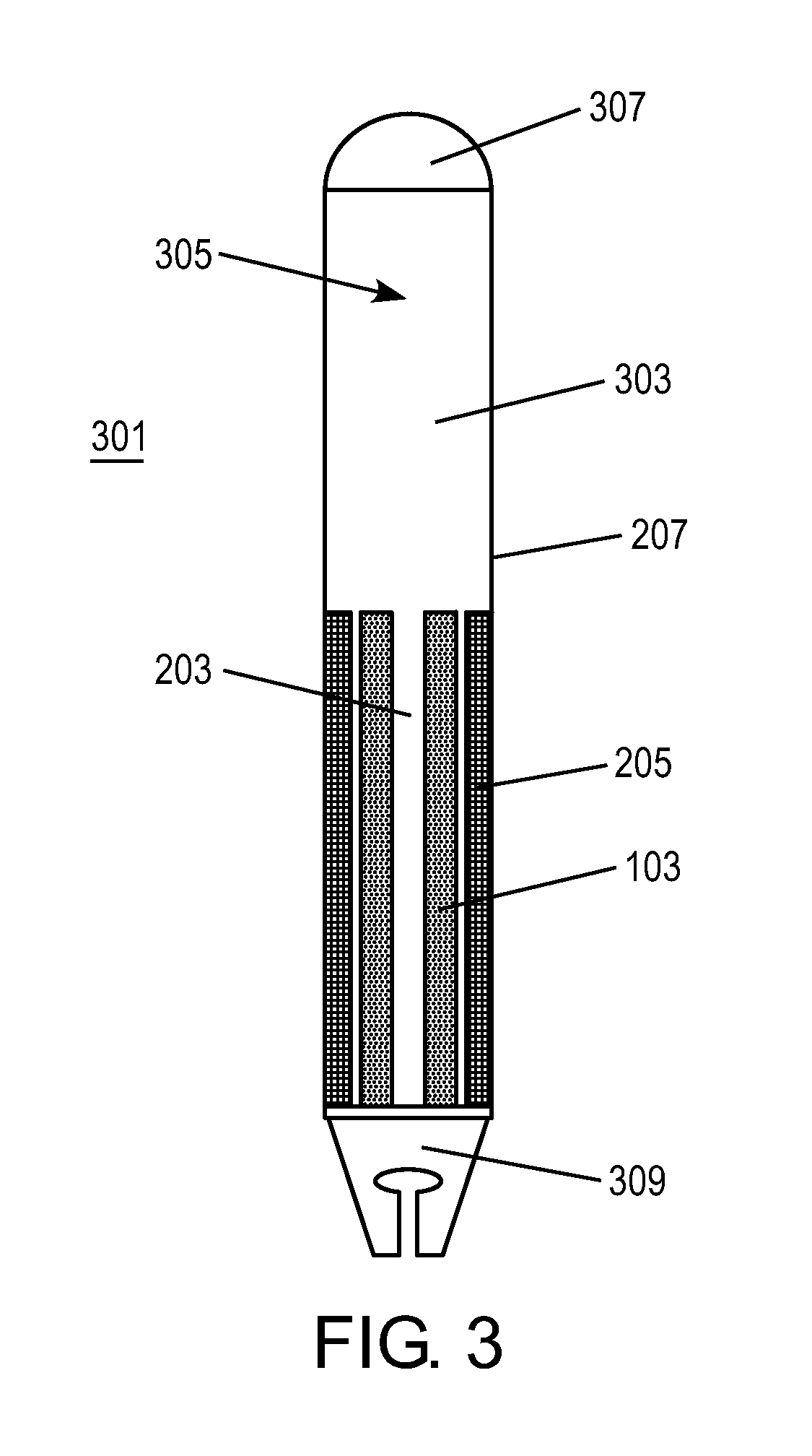
[0014]Embodiments of the present invention may include sheathed, annular metal nuclear fuels, mold arrangements for sheathed, annular metal nuclear fuels, and methods for fabrication of sheathed, annular metal nuclear fuels.

[0015]In certain embodiments, several fabrication techniques may be used separately and / or individually to create the sheathed, annular metal nuclear fuels. For example, fabrication of annular metal fuels may be performed by bottom pour casting of a solid slug of metal fuel into a zirconium or similar type of tube in a graphite mold.

[0016]Embodiments of the present invention may include fabrication and irradiation of an annular metal fuel slug with a zirconium sheath that is fit tightly to a cladding, which may be steel, with a helium bond. This combination can provide a number of important attributes that each feature, when taken individually, would not.

Fabrication Process

[0017]FIG. 1 shows a mold arrangement 101 for bottom pour casting according to one embodime...


PUM

PropertyMeasurementUnit
Diameteraaaaaaaaaa

Abstract

A sheathed, annular metal fuel system is described. A metal fuel pin system is described that includes an annular metal nuclear fuel alloy. A sheath may surround the metal nuclear fuel alloy, and a cladding may surround the sheath. A gas plenum may also be present. Mold arrangements and methods of fabrication of the sheathed, annular metal fuel are also described.

Description

CROSS REFERENCE TO RELATED APPLICATION[0001]The present invention claims priority to U.S. Provisional Patent Application No. 61 / 294,673, filed Jan. 13, 2010; the content of which is incorporated herein by reference in its entirety.TECHNICAL FIELD OF THE INVENTION[0002]The present invention is related to nuclear fuels, and, more particularly, to metal nuclear fuel.BACKGROUND OF THE INVENTION[0003]World electricity demand is expected to double by 2030 and quadruple by 2050. The world electricity demand increase is forecasted to come from developed countries and, to an even larger extent, developing countries. To meet this rapid growth in demand, nuclear power may be a realistic, cost-effective energy source.[0004]Increased energy supply from other sources, such as contribution from natural gas powered generation may be constrained by high and volatile gas prices, greenhouse gas emissions, and concerns over longer-term dependence on unstable sources of supply. Meanwhile, forms of alter...

Claims


Application Information

Patent Timeline
IPC IPC(8): G21C3/00B22D11/04B22D23/00
CPCG21C3/04G21C3/06Y02E30/38G21C21/02G21C3/60Y02E30/30B22D19/00B22D21/022B22D21/025B22D27/003G21C3/38
Inventor WALTERS, LEON C.
Owner ADVANCED REACTOR CONCEPTS
Why Eureka
Try Eureka