Multiple Power Control Parameter Sets for Wireless Uplink Data Transmission

a technology of power control and data transmission, applied in power management, electrical equipment, radio transmission, etc., can solve the problems of significant intra-cell interference, signal transmission from different ues is not ideal, and radio signals are typically not orthogonal, so as to increase the overall performance of the relaying system and increase the spatial coverage of the lte network cells

Inactive Publication Date: 2011-08-11
NOKIA SOLUTIONS & NETWORKS OY +1
View PDF39 Cites 74 Cited by
  • Summary
  • Abstract
  • Description
  • Claims
  • Application Information

AI Technical Summary

Benefits of technology

[0017]In particular, by allowing one and the same UE to select one set out of at least two sets of power control parameters for transmitting uplink to the base station, a “strong UE” having a high quality radio data connection to the base station can obtain the capability to be considerate of the situation of a “weak UE” having a poor quality radio data connection to the base station. This may mean that the “strong UE” can use the less aggressive set of power control parameters for transmitting its uplink (UL) signals with a smaller transmitting power as compared to a situation without the weak UE being present.
[0057]In particular, the possibility to increase the overall performance of a relaying system with respect to the data throughput may represent a great improvement for future Long Term Evolution (LTE) telecommunication networks in order to increase the spatial coverage of LTE network cells.

Problems solved by technology

The reason is that the radio signals being transmitted by different User Equipments (UE) are typically not ideally orthogonal.
This leads at least to some significant intra-cell interference.
However, also in a telecommunication network operating with Orthogonal Frequency Division Multiple Access (OFDMA) the signals being transmitted from different UEs are not ideally separated because of physical and / or technical limitations, which cannot be avoided.
Such limitations are for instance (a) the Doppler Effect, if the corresponding UE is moving relative to its serving base station, (b) a non-ideal synchronization of local oscillators of the different UE, (c) non linearities within the radio signal transmission and / or the radio signal reception and / or (d) a limited resolution of analog-to-digital conversion procedures.
These limitations lead to the fact that there is always at least some leakage from one UE's radio signal to another UE's radio signal.
This leakage limits the dynamic range of a base station's receiver structure.
In other words, the receiver structure cannot resolve different signals from each other which exhibit large differences in receive level.
Due to the above described leakage, it would not be possible to resolve the weak signal from the far UE from the strong signal from the close UE.
However, this has the consequence that UE being currently situated close to the base station do not really benefit from the fact that they have a very small pathloss and probably do not cause interference to the other cells.
This limitation is in particular harmful, if features and / or extensions of the cellular telecommunication network are based on a very high data rate.
Due to the power control restrictions elucidated above, the good radio transmission channel conditions on the radio link between base station and relay node cannot be fully exploited.
Accordingly, similarly to UEs being located close to the base station also Relay Nodes are not able to realize high data rates with the base station.

Method used


Image

  • Multiple Power Control Parameter Sets for Wireless Uplink Data Transmission
  • Multiple Power Control Parameter Sets for Wireless Uplink Data Transmission
  • Multiple Power Control Parameter Sets for Wireless Uplink Data Transmission

Examples


Embodiment Construction

[0071]The illustration in the drawing is schematically. It is noted that in different figures, similar or identical elements are provided with the same reference signs or with reference signs, which are different from the corresponding reference signs only within the first digit.

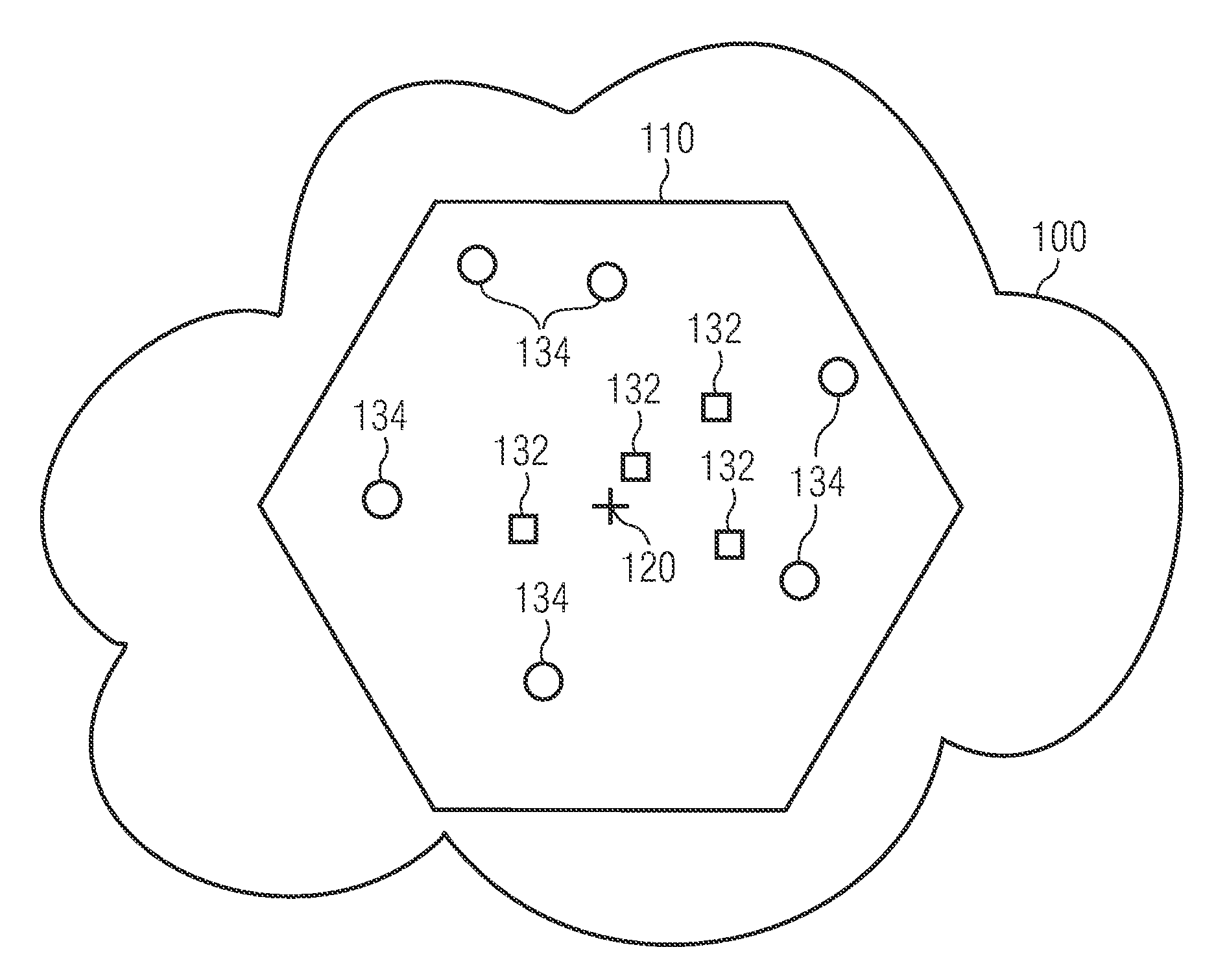
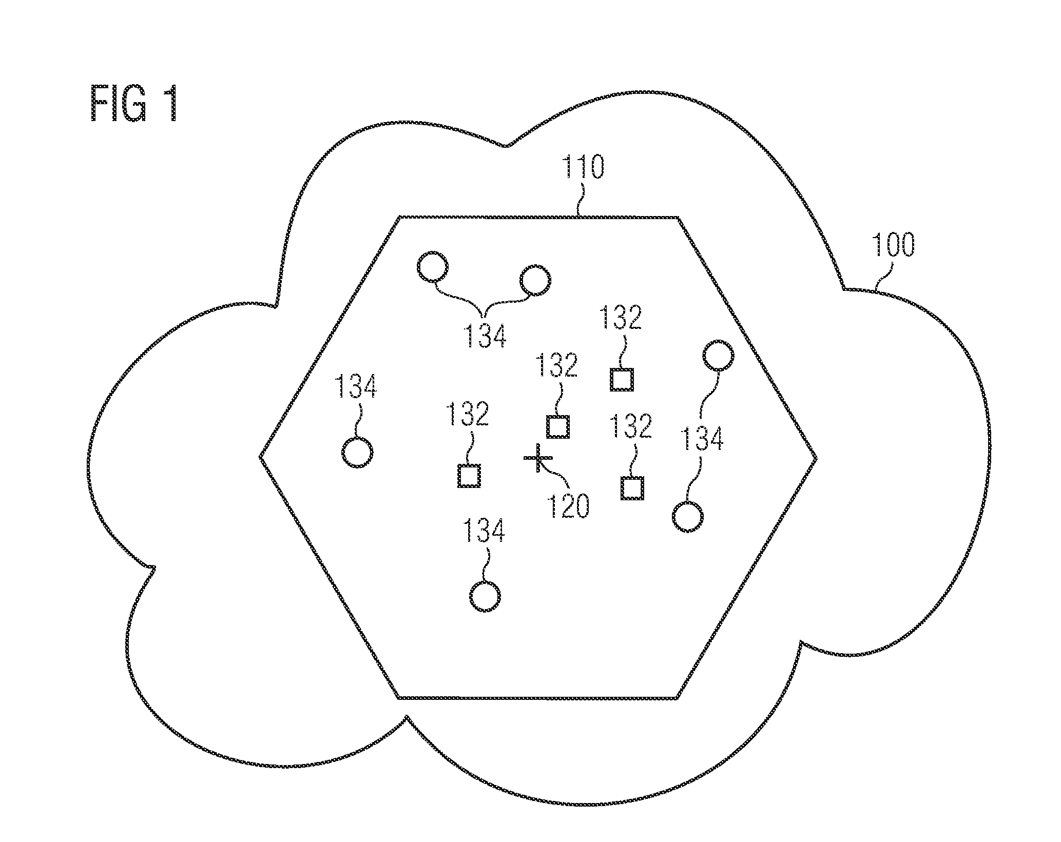
[0072]FIG. 1 shows a cellular telecommunication network 100. The cellular telecommunication network 100 comprises a plurality of cells, wherein in FIG. 1 only one cell 110 is depicted for the sake of clarity. The cell 110 is served by a base station 120. In the framework of Universal Mobile Telecommunications System (UMTS) the base station is called a NodeB. In the framework of Long Term Evolution (LTE) networks, the base station is typically called an enhanced NodeB (eNB).

[0073]Within the cell 110 there is located a plurality of network elements 132, 134. Each network element 132, 134 may be (a) a user equipment (UE) such as for instance a cellular phone, a personal digital assistant (PDA) or a notebook com...


PUM


Abstract

It is described a method for controlling the transmission power for a network element being connected to a base station of a cellular telecommunication network via an uplink wireless data connection. The method including providing a first set (set1) of power control parameters (P0<sub2>—< / sub2>PUSCH<sub2>—< / sub2>1, α1) and a second set (set2) of power control parameters (P0<sub2>—< / sub2>PUSCH<sub2>—< / sub2>2, α2), storing the first set (set1) of power control parameters (P0<sub2>—< / sub2>PUSCH<sub2>—< / sub2>1, α1) and the second set (set2) of power control parameters (P0<sub2>—< / sub2>PUSCH<sub2>—< / sub2>2, α2) within the network element, using the first set (set1) of power control parameters (P0<sub2>—< / sub2>PUSCH<sub2>—< / sub2>2, α1) by the network element for transmitting within a first radio transmission resource, and using the second set (set2) of power control parameters (P0<sub2>—< / sub2>PUSCH<sub2>—< / sub2>2, α2) by the network element for transmitting within a second radio transmission resource. Further, it is described a network element and a base station, which are, in connection with each other, adapted to carry out the described transmission power controlling method.

Description

FIELD OF INVENTION[0001]The present invention relates to the field of operating cellular telecommunication networks. In particular, the present invention relates to a method for controlling the transmission power for a network element being connected to a base station of a cellular telecommunication network via an uplink wireless connection. Further, the present invention relates to a network element and to a base station, which are, in connection with each other, adapted to carry out the described transmission power controlling method. Furthermore, the present invention relates to a computer program, which, when executed by means of a processor, is adapted to carry out the described transmission power controlling method.ART BACKGROUND[0002]Uplink power control is a mandatory feature for every multiple access telecommunication system which is not based purely on the principles of Time Division Multiple Access (TDMA). The reason is that the radio signals being transmitted by differen...

Claims


Application Information

Patent Timeline
Patent Type & Authority Applications(United States)
IPC IPC(8): H04W52/04H04W72/04
CPCH04W52/346H04W52/146H04W52/322H04W52/325
Inventor IRMER, RALFRAAF, BERNHARDVIERING, INGO
Owner NOKIA SOLUTIONS & NETWORKS OY
Why Eureka
Try Eureka