

Hybrid power device
a hybrid power fet and power electronics technology, applied in the direction of oscillator generators, electronic switching, pulse techniques, etc., can solve the problems of adversely increasing switching loss, high reliability, and inconvenient use of sic-jfet in power electronics devices, so as to reduce the switching loss and suppress resonance
- Summary
- Abstract
- Description
- Claims
- Application Information
AI Technical Summary
Benefits of technology
Problems solved by technology
Method used
Image

Examples
first embodiment
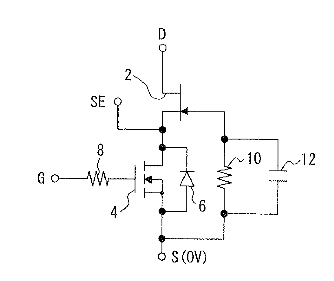
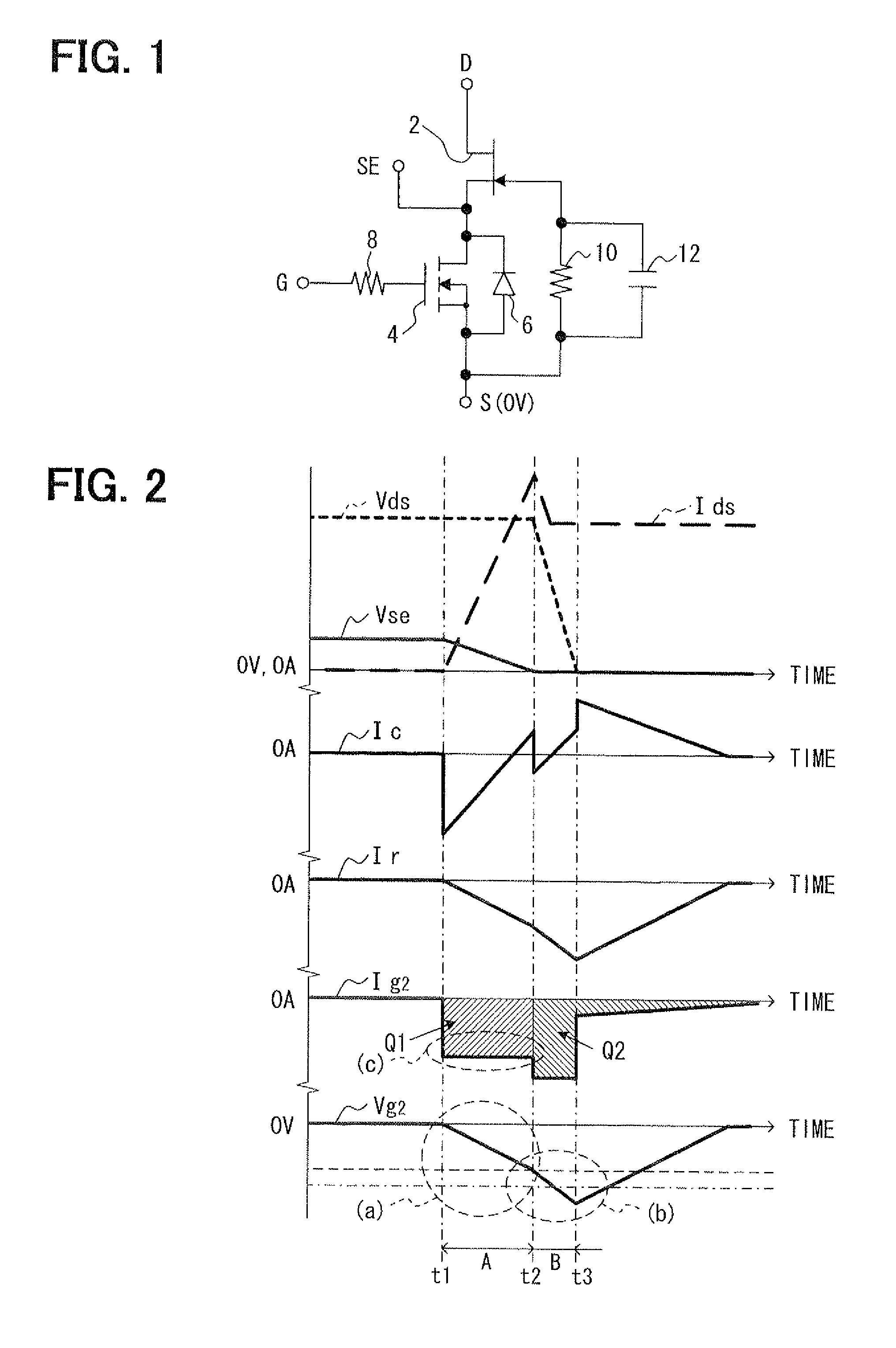
[0028]Referring first to FIG. 1, a first hybrid power device according to a first embodiment is formed of a normally-on type SiC-JFET 2 and a normally-off type Si-MOSFET 4. The source of the SiC-JFET 2 and the drain of the Si-MOSFET 4 are connected to each other so that the SiC-JFET 2 and the Si-MOSFET 4 are connected in cascade. This basic configuration is similar to that shown in FIG. 8 and form a hybrid power FET.
[0029]The first hybrid power device is however different from that shown in FIG. 8 in that, in a control circuit part for the hybrid power FET, a capacitor 12 is connected in parallel to a speed regulating resistor 10, which is provided between the gate of the SiC-JFET 2 and the source of the Si-MOSFET 4 as a control element for controlling a switching speed of the hybrid power device. Since the capacitor 12 is connected in parallel to the speed regulating resistor 10, the switching speed is controllable by the capacitor 12 in a switching period.
[0030]This control is des...
second embodiment
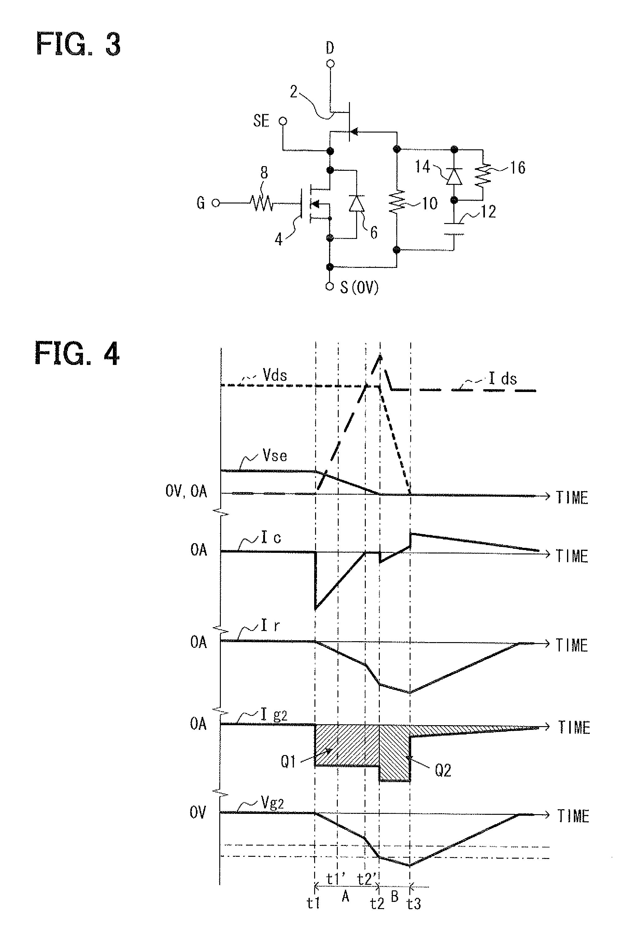
[0036]In a second hybrid power device according to a second embodiment, as shown in FIG. 3, a parallel circuit of a diode 14 and a parallel resistor 16 are connected in series with the capacitor 12. The diode 14 and the parallel resistor 16 are connected in parallel to each other. The second hybrid power device has the same structure as that of the first embodiment in other respects. The diode 14 is reverse-biased with its anode and cathode connected to the capacitor 12 and the gate of the SiC-JFET 2, respectively. The resistance of the parallel resistor 16 is set to be smaller than that of the resistor 10.
[0037]In the second hybrid power device, as shown in FIG. 4, the current primarily flows through the diode 14 in a former period (time t1 to time t1′) in the first stage A when the Si-MOSFET 4 turns on. The capacitor 12 is charged in a subsequent period (time t1′ to time t2′) in the first stage A, and starts discharge after time t2′.
[0038]Since the diode 14 is reverse-biased at th...
third embodiment
[0040]In a third hybrid power device according to a third embodiment, as shown in FIG. 5, the capacitor 12 of the control circuit part is connected between the gate of the SiC-JFET 2 and the gate of the of the Si-MOSFET 4 differently from the first embodiment, in which it is connected in parallel to the resistor 10. The third hybrid power device has the same structure as that of the first embodiment in other respects.
[0041]The capacitor 12 is connected to a drive circuit for the Si-MOSFET 4 directly in the end. Delay in operation of the SiC-JFET 2 relative to the on / off operation of the Si-MOSFET 4 is thus reduced. Accordingly, the switching speed is increased and transient voltage change of the Si-MOSFET 4 is suppressed.
[0042]That is, the switching speed is increased by relatively speeding up the operation of the SiC-JFET 2 in the third embodiment, as opposed to the first embodiment, in which the SiC-JFET 2 starts to operate with delay after the on / off switching operation of the Si...
PUM
 Abstract
Description
Claims
Application Information