Non-reflective imaging optics for optical devices, particularly in ophthalmology

a technology of optical devices and non-reflective imaging, which is applied in the field of ophthalmology, can solve the problems of negative effect of great working distance on the frame size of the mirror elements, and achieve the effects of good optical quality, large field of view, and great working distan

Active Publication Date: 2011-08-18
CARL ZEISS MEDITEC AG
View PDF7 Cites 9 Cited by
  • Summary
  • Abstract
  • Description
  • Claims
  • Application Information

AI Technical Summary

Benefits of technology

[0020]Through the use of free-form geometries, it is possible to achieve a great working distance and a large field of view with good optical quality. However, for the suggested basic design, the great working distance has a negative effect o

Problems solved by technology

However, for the suggested basic design, the great working distan

Method used


Image

  • Non-reflective imaging optics for optical devices, particularly in ophthalmology
  • Non-reflective imaging optics for optical devices, particularly in ophthalmology
  • Non-reflective imaging optics for optical devices, particularly in ophthalmology

Examples


Embodiment Construction

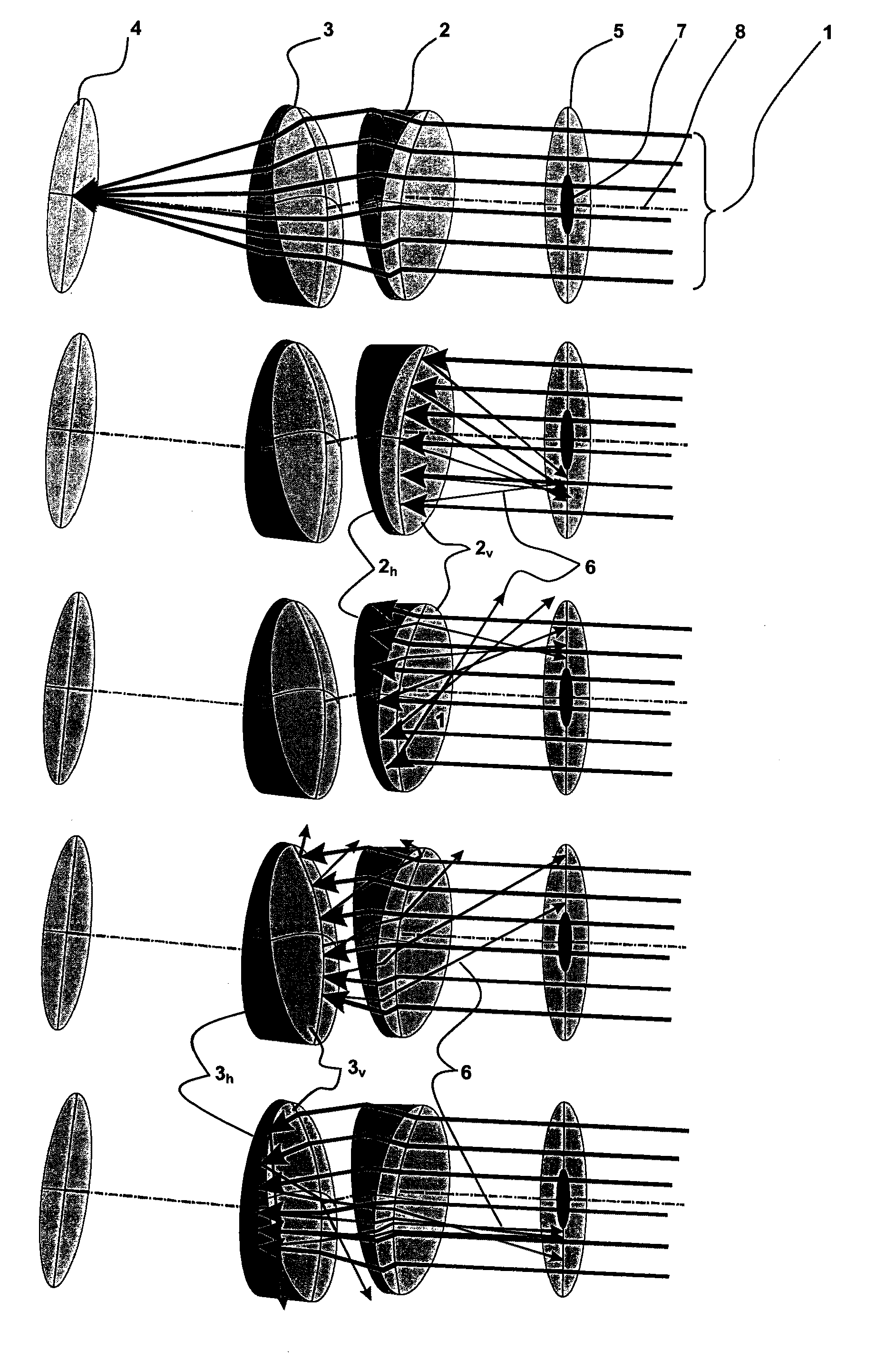
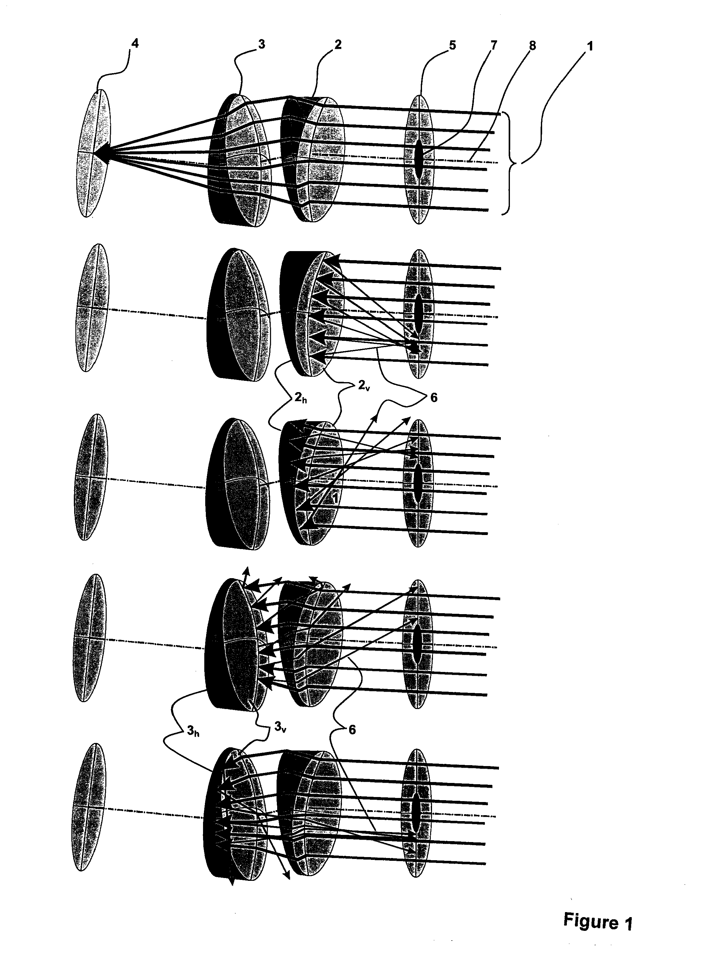
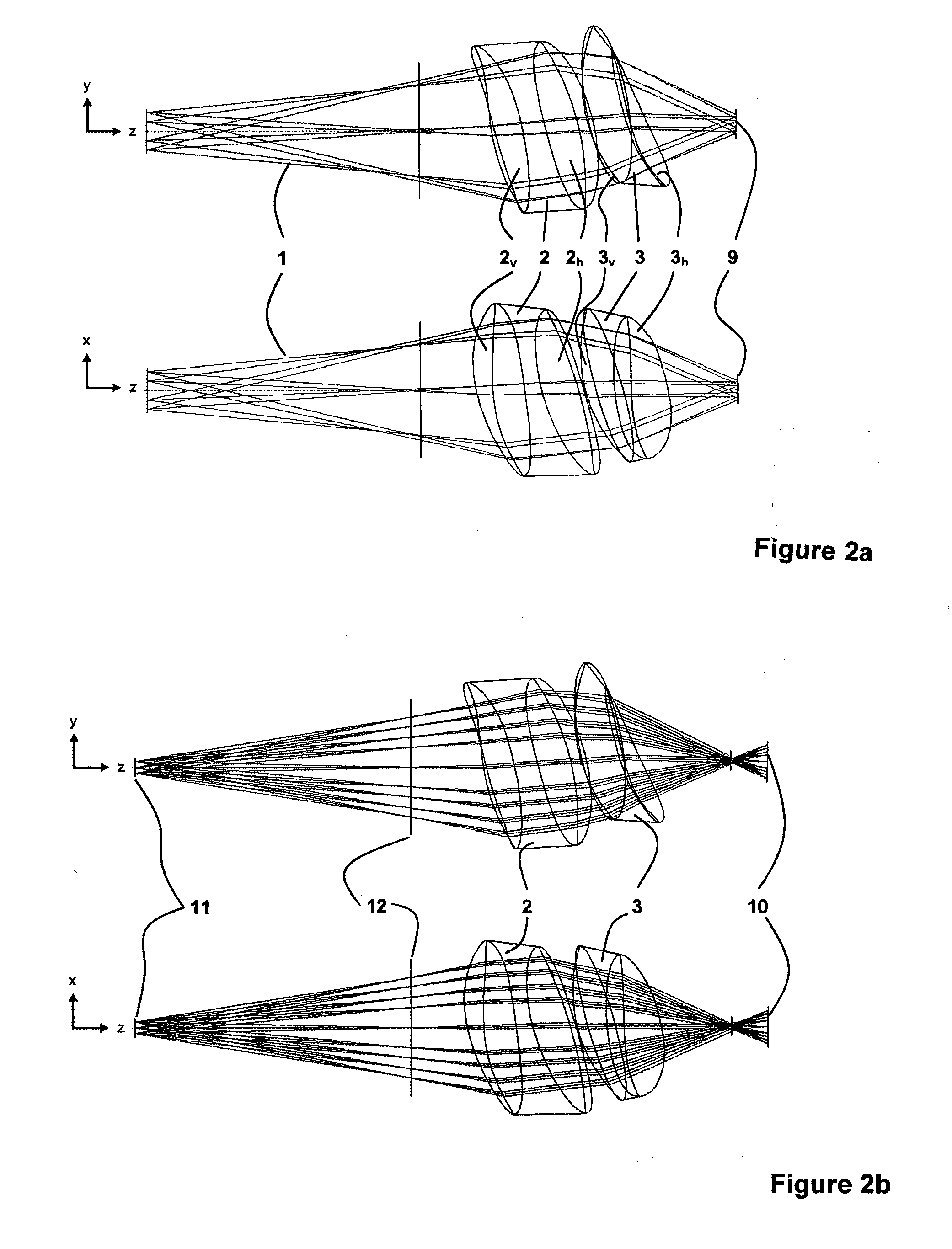
[0036]According to the invention, the non-reflective imaging optics for optical devices, particularly in ophthalmology, consist of at least two refractive optical elements, which are utilized for illumination as well as observation. Thereby, the at least two refractive optical elements are designed approximately wedge-shaped and are tilted at a random azimuth angle of at least 5° and / or are positioned off-center in the beam path in order to block out the single reflections of the illumination, occurring at the optical system surfaces, for the observation.

[0037]Tilting the refractive optical elements and / or their system surfaces refers to the tilting of optically active surfaces with regard to the reference axis in at least one azimuth. The reference axis is identical with the beam which runs through the center of the field stop and aperture diaphragm. Through tilting of a surface, the reference axis and the face normal form a nonzero degree angle at the intersection point of the ref...


PUM


Abstract

Imaging optics for optical devices, with which reflections of the illumination light, which is guided through the same optical elements as the observation light, are kept from reaching the observation pupil of the imaging beam path. The non-reflective imaging optics include at least two refractive optical elements, which are utilized for illumination as well as observation. The at least two refractive optical elements are designed approximately wedge-shaped and are tilted at a random azimuth angle of at least 5° and/or are positioned off-center in the beam path to block out the single reflections of the illumination, occurring at the optical system surfaces, for the observation. The imaging optics are for optical devices, particularly in ophthalmology thought the invention is applicable to other ophthalmological devices as well as to optical devices outside of this field.

Description

[0001]This application claims priority to German Patent Application No. 102010008629.0 filed on Feb. 17, 2009, said application is incorporated herein by reference in its entirety.BACKGROUND OF THE INVENTION[0002]The invention is applicable particularly advantageously in cases in which the area to be observed, illuminated by the illumination, exhibits a very low reflectivity; as a result, the intensity, of the reflections of the illumination at optical boundary layers of the system, exceeds the utility light intensity or significantly interferes with the latter. Such systems include, for example, the ophthalmoscopic lens of a fundus camera used for the mapping of the eyeground since the degree of reflection of the fundus to be observed is very low.[0003]According to known prior art, the basic design of a fundus camera exhibits a multilevel optical system. Thereby, an intermediate image of the retina is produced by an ophthalmoscopic lens, which is then mapped by an optical tracking ...

Claims


Application Information

Patent Timeline
IPC IPC(8): A61B3/10G02B5/00
CPCG02B13/18A61B3/156G02B27/0018G02B13/24
Inventor BUCHHEISTER, JANMULLER, LOTHARPRETORIUS, MARCO
Owner CARL ZEISS MEDITEC AG
Why Eureka
Try Eureka