Method of initializing magnetic memory element

a magnetic memory element and initialization technology, applied in the field of initializing magnetic memory elements, can solve the problems of increasing the chip area and power consumption for writing, increasing the write current, and mram being inferior to other random access memories, so as to increase the allowed range of magnetic field magnitude

Active Publication Date: 2011-08-18
NEC CORP
View PDF2 Cites 9 Cited by
  • Summary
  • Abstract
  • Description
  • Claims
  • Application Information

AI Technical Summary

Benefits of technology

[0018]According to the present invention, a technique is provided which increases the allowed range of the magnitude of the magnetic field applied for the initialization of the magnetic memory element provided with the data recording layer having perpendicular magnetic anisotropy.

Problems solved by technology

This undesirably increases the chip area and power consumption for writing and such MRAM is inferior to other random access memories in competitiveness.
In addition, when the element is reduced in size, the write current further increases, which is undesirable also in scaling.
However, a dielectric layer is generally provided between the first magnetic layer and the second magnetic layer and a relatively large current must be flown through the dielectric layer in a write operation, which causes problems in terms of rewriting resistance and reliability.
Moreover, since a current path in the write operation is same as that in the read operation, this may cause unintentional writing in the read operation.
As described above, despite of the excellent scaling property, the spin injection magnetization reversal has some obstacles to practical utilization.
This does not satisfy the above-mentioned requirement for the write current.
However, according to such an initialization method in which a stepped structure is provided and a domain wall is introduced by using a magnetic field perpendicular to the substrate surface, the magnitude of the applied magnetic field is limited within a certain allowed range.
When the allowed range is narrow, problems such as reduction in yield occur in manufacturing large-capacity magnetic memories.

Method used


Image

  • Method of initializing magnetic memory element
  • Method of initializing magnetic memory element
  • Method of initializing magnetic memory element

Examples


first modification

(First Modification)

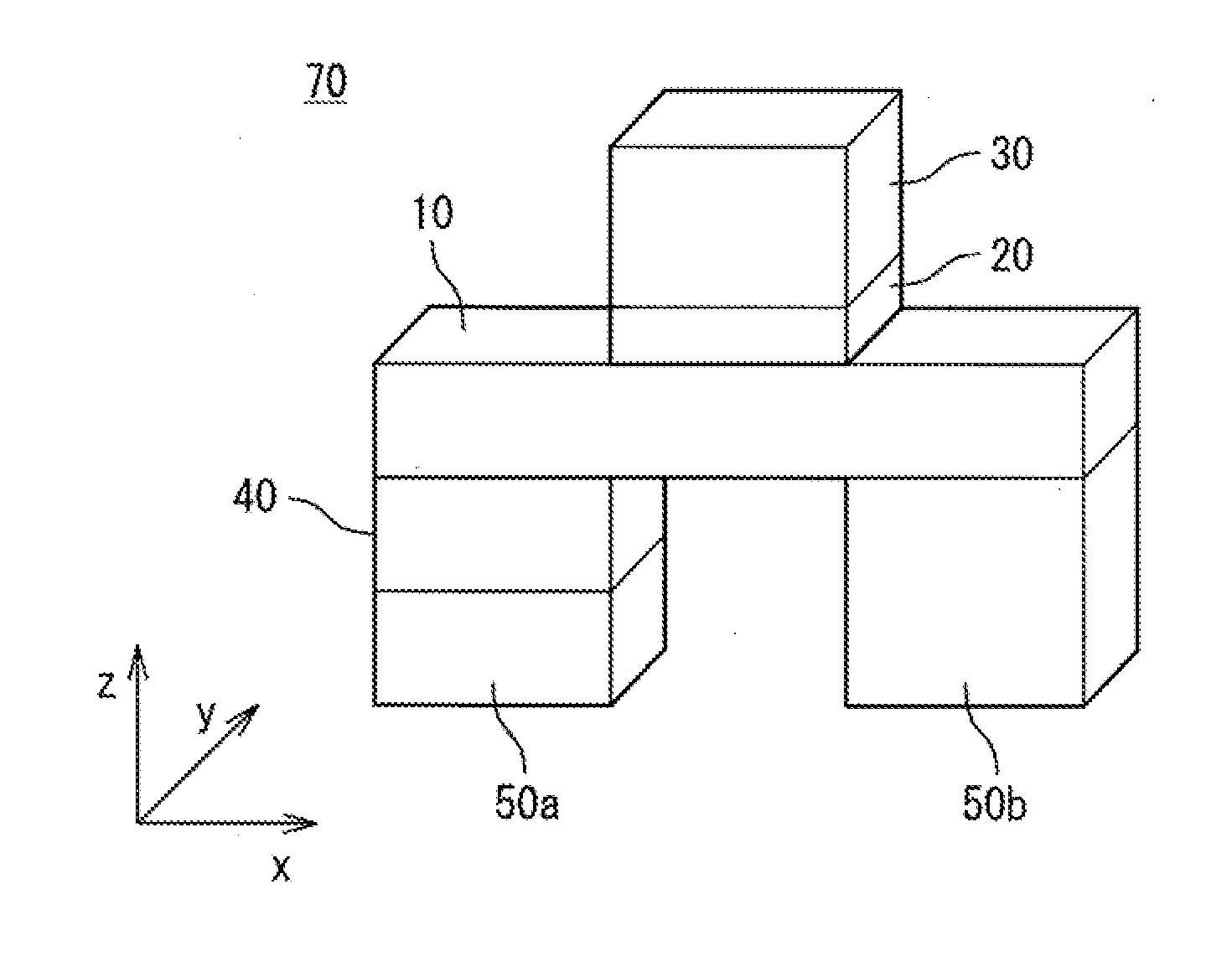
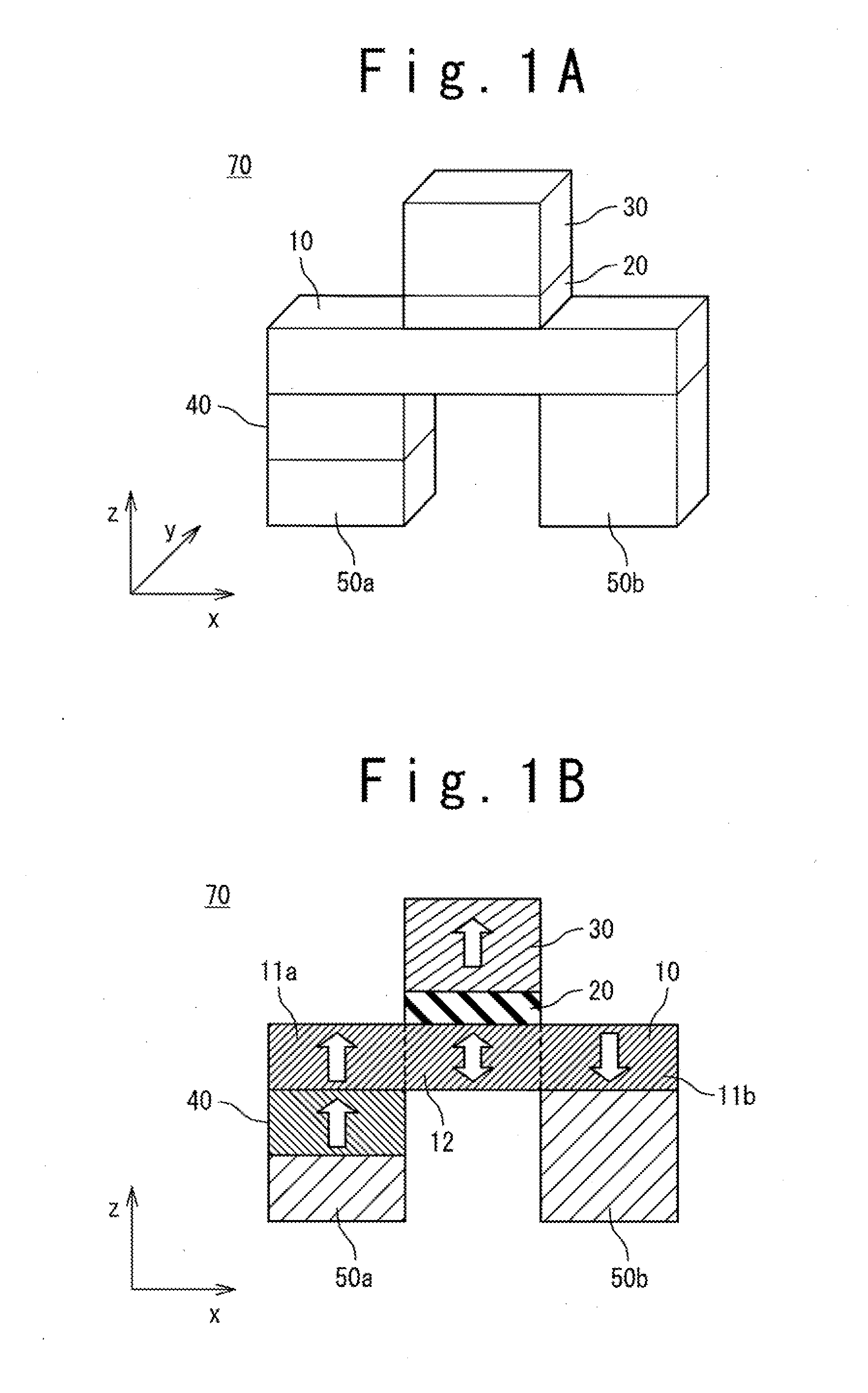
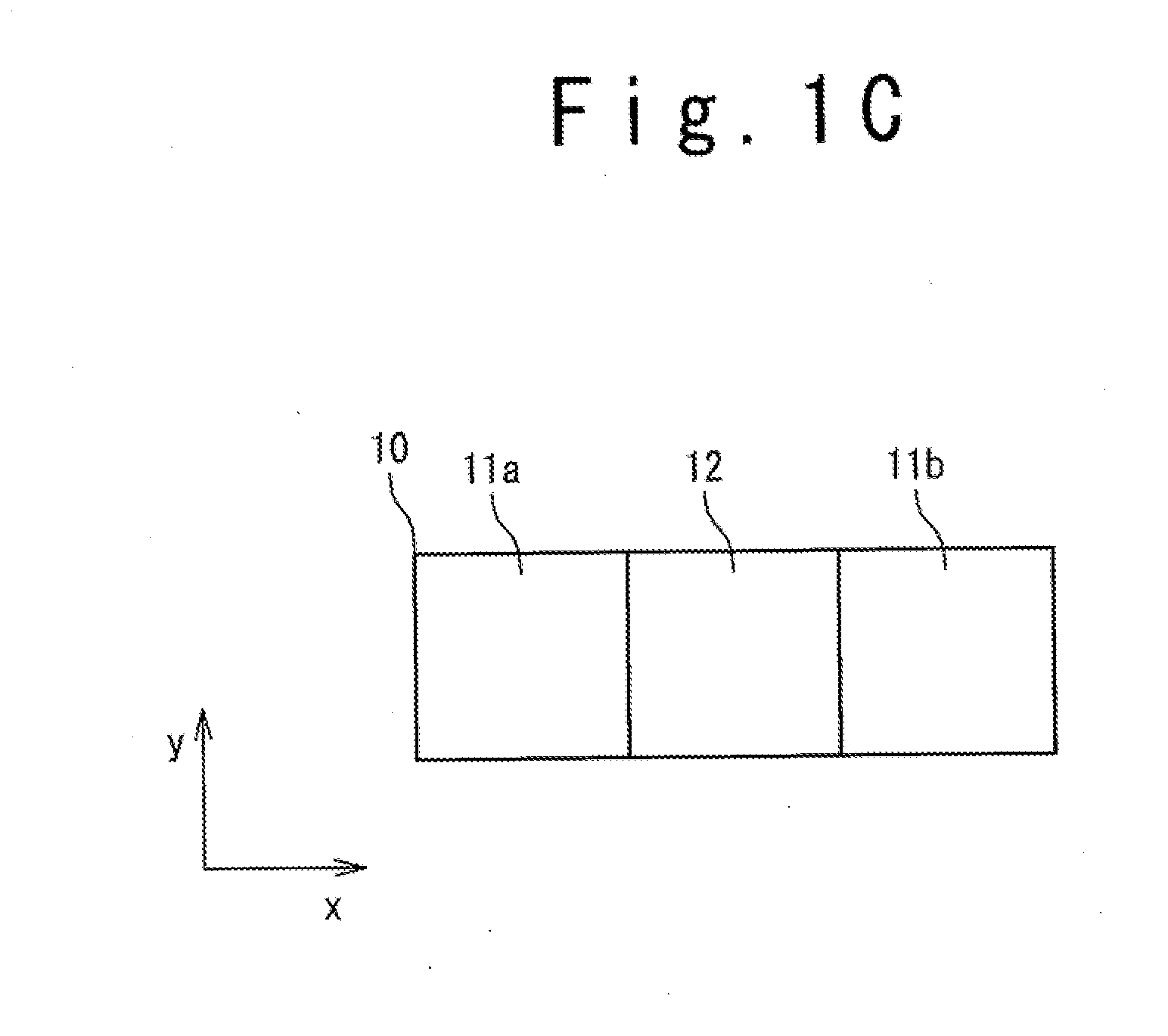
[0112]FIGS. 13A and 13B schematically show a first modification of the magnetic memory element, specifically, junctions between the data recording layer 10 and the auxiliary ferromagnetic layer 40 (40a, 40b) in the magnetic memory element 70.

[0113]The number of the auxiliary ferromagnetic layers 40 provided for the magnetic memory element 70 is optional. That is, two auxiliary ferromagnetic layers 40 may be provided as shown in FIG. 13A or only one auxiliary ferromagnetic layer 40 may be provided as shown in FIG. 13B. Alternatively, three or more auxiliary ferromagnetic layers 40 may be provided. In the example shown in FIG. 13A, a first auxiliary ferromagnetic layer 40a and a second auxiliary ferromagnetic layer 40b are provided adjacent to the first magnetization fixed region 11a and the second magnetization fixed region 11b, respectively.

[0114]When a plurality of auxiliary ferromagnetic layers are provided as shown in FIG. 13A, the auxiliary ferromagnetic laye...

second modification

(Second Modification)

[0117]FIGS. 14A and 14B schematically show a second modification of the magnetic memory element, more specifically, the junction between the data recording layer 10 and the auxiliary ferromagnetic layer 40 in the magnetic memory element 70. The position of the auxiliary ferromagnetic layer 40 is optional. That is, the auxiliary ferromagnetic layer 40 may be joined to the lower surface of the first magnetization fixed region 11a of the data recording layer 10 as shown in FIG. 14A, or may be joined to the upper surface of the first magnetization fixed region 11a as shown in FIG. 14B. Further, the auxiliary ferromagnetic layer 40 may be joined laterally to the data recording layer 10.

third modification

(Third Modification)

[0118]FIGS. 15 to 18 show a third modification of the magnetic memory element, specifically, various structures of the domain wall introduction mechanism provided in the magnetic memory element 70. The domain wall introduction mechanism for introducing the domain wall into the data recording layer 10, which is provided in the magnetic memory element 70, may be variously structured. In detail, although an example in which the auxiliary ferromagnetic layer 40 made of ferromagnetic material is provided as the domain wall introduction mechanism has been described above, a domain wall introduction mechanism with a different structure may be adopted.

[0119]FIG. 15 shows an example of the domain wall introduction mechanism. In FIG. 15, an antiferromagnetic layer 41 made of antiferromagnetic material is provided as the domain wall introduction mechanism. Examples of antiferromagnetic materials that can be used for the antiferromagnetic layer 41 include Pt—Mn and Ir—Mn. Th...


PUM


Abstract

An initialization method is provided for a magnetic memory element including: a data recording layer having perpendicular magnetic anisotropy which includes: a first magnetization fixed region, a second magnetization fixed region, and a magnetization free region coupled to the first magnetization fixed region and the second magnetization fixed region, the data recording layer being structure so that the coercive force of the first magnetization fixed region being different from that of the second magnetization fixed region. The initialization method includes steps of: directing the magnetizations of the first magnetization fixed region, the second magnetization fixed region and the magnetization free region in the same direction; and applying a magnetic field having both components perpendicular to and parallel to the magnetic anisotropy of the data recording layer to the data recording layer.

Description

TECHNICAL FIELD[0001]The present invention relates to a method of initializing a magnetic memory element, in particular, to a technique of initially introducing a domain wall into a data recording layer of the magnetic memory element.BACKGROUND ART[0002]Magnetic memories or magnetic random access memories (MRAM), which operate as nonvolatile memories capable of performing a high-speed operation and rewriting of an infinite number of times, have been put into practical use in specific applications and developed to improve versatility. In an MRAM, a magnetic memory element using a magnetic film is used as a memory cell and data is stored as the direction of the magnetization of the magnetic film. Typically, a magnetic memory element includes two magnetic layers and a nonmagnetic layer interposed between the magnetic layers. To read data from the magnetic memory element, a magnetoresistance effect revealed between the first and second magnetic layers, specifically, a TMR effect (tunnel...

Claims


Application Information

Patent Timeline
Patent Type & Authority Applications(United States)
IPC IPC(8): G11C11/14
CPCG11C11/16H01L43/08H01L27/228G11C11/1655G11C11/1659G11C11/161G11C11/1673G11C11/1675H10B61/22H10N50/10
Inventor FUKAMI, SHUNSUKENAGAHARA, KIYOKAZUSUZUKI, TETSUHIROISHIWATA, NOBUYUKIOHSIMA, NORIKAZU
Owner NEC CORP
Why Eureka
Try Eureka