Process for producing thermoplastic resin foam film and thermoplastic resin foam film

Inactive Publication Date: 2011-08-18
KANEKA CORP
View PDF4 Cites 5 Cited by
  • Summary
  • Abstract
  • Description
  • Claims
  • Application Information

AI Technical Summary

Benefits of technology

[0012]The process for producing a thermoplastic resin foam film according to the present invention provides a thermoplastic resin foam film higher in thickness accuracy. In addition, the thermoplastic resin foam

Problems solved by technology

However, such foams, which are deformable as they are held densely between two articles, are unfavorable for the core region of layered structures.
However, the foam film is drawn more in the extrusion direction for increase of heat shrinkage and the cells therein are flattened significantly in the thickness direction and unfavorably lower in compressive strength.
However, the process described in Patent Document 3 is aimed at cutting processing without destruction of surface cells, and there is no description on production of a foam film higher in thickness accuracy.
When a band saw

Method used


Image

  • Process for producing thermoplastic resin foam film and thermoplastic resin foam film
  • Process for producing thermoplastic resin foam film and thermoplastic resin foam film
  • Process for producing thermoplastic resin foam film and thermoplastic resin foam film

Examples


example 1

[0058]A rectangular body foam of 450 mm×300 mm×25 mm having a density of 210 kg / m3 was prepared by preliminary expansion and molding of a heat-resisting expandable styrenic resin (low expansion ratio), Heatmax (trade name) HM5 manufactured by KANEKA CORPORATION. The rectangular foam was cut to a desired thickness of 0.3 mm by using the following cutting machine.

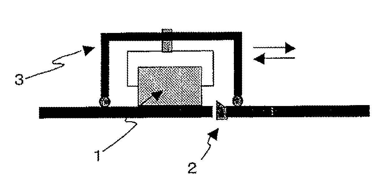
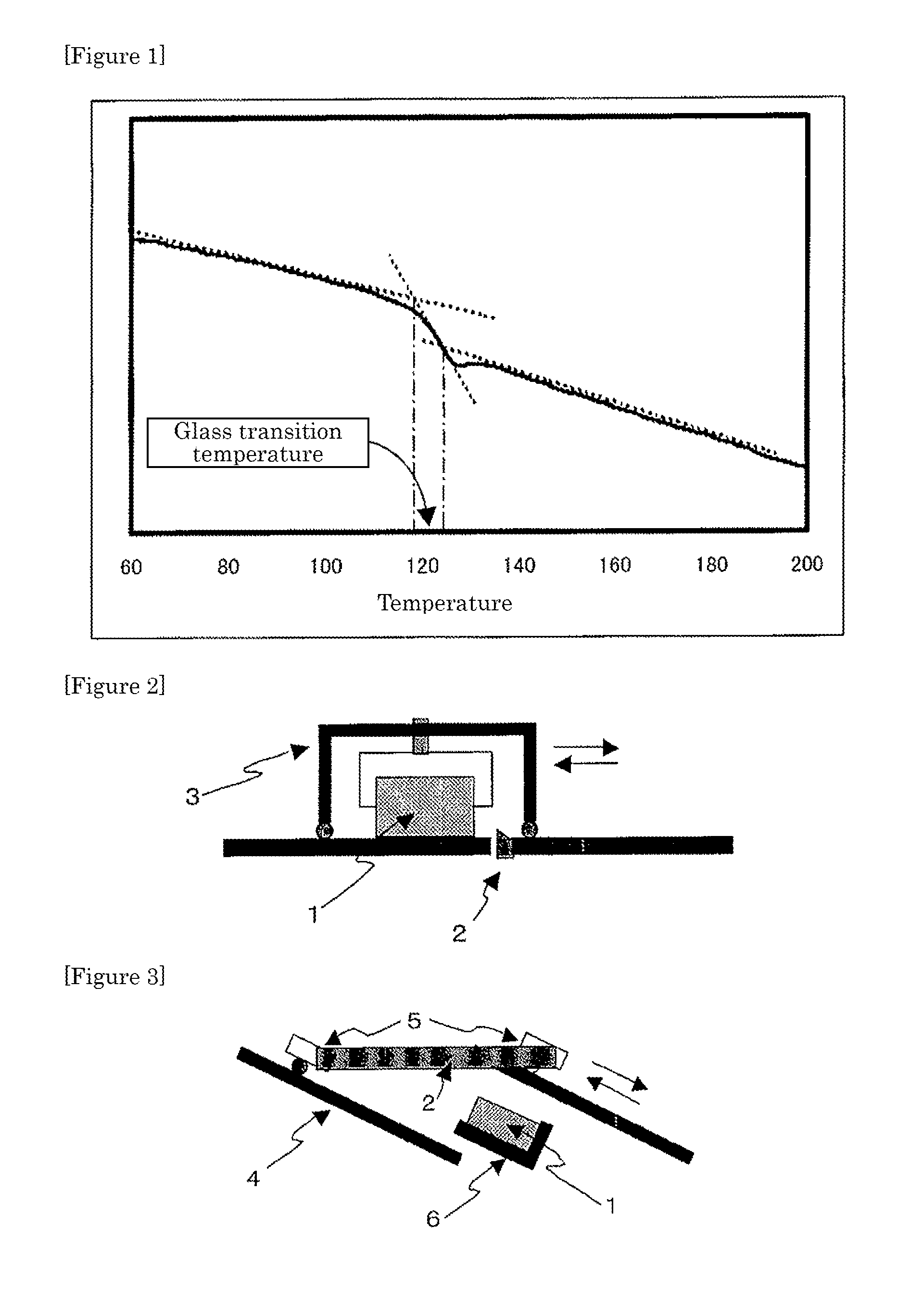
[0059]The cutting machine used is a wood-processing cutting machine having a supporting plate moving reciprocally on a rail in parallel with the floor face, in which a foam is cut continuously, as it is connected to the lower area of the supporting plate, reciprocated on the blade fixed facing upward for cutting, pushed downward at a desired cutting thickness after each cutting, i.e., after each reciprocation. The bias angle was set to 10°.

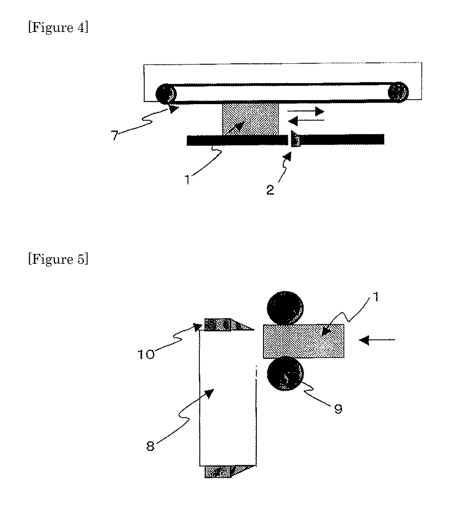
[0060]The thin film obtained by cutting was a film a highly curled into a roll having a diameter of about 15 mm, but, when the film is held extended between two aluminum plates, heated in a...

example 2

[0062]The rectangular foam obtained in Example 1 was cut to a desired thickness of 0.7 mm by using the same cutting machine used in Example 1 and converted into a flat film in a manner similar to Example 1. Evaluation results are shown in Table 1. Lamination of an aluminum foil having a thickness of 0.012 mm in a manner similar to Example 1 gave a high-rigidity laminate foam film.

example 3

[0063]A rectangular body foam of 450 mm×300 mm×25 mm having a density of 140 kg / m3 was prepared by preliminary expansion and molding of a heat-resisting expandable styrenic resin (low expansion ratio), Heatmax (trade name) HM5 manufactured by KANEKA CORPORATION, and the rectangular body foam was cut to a desired thickness of 0.3 mm and flattened in a manner similar to Example 1. Evaluation results are shown in Table 1. An aluminum foil having a thickness of 0.012 mm was bonded in a manner similar to Example 1, to give a high-rigidity laminate foam film.


PUM

PropertyMeasurementUnit
Fractionaaaaaaaaaa
Thicknessaaaaaaaaaa
Thicknessaaaaaaaaaa

Abstract

Disclosed is a process for producing a thermoplastic resin foam film that can produce a thin thermoplastic resin foam film. The process comprises the step of cutting a thermoplastic resin foam. The process is characterized in that, in the step of cutting the thermoplastic resin foam, at least one of the thermoplastic resin foam and a blade is reciprocated, and, when at least one of the thermoplastic resin foam and the blade is reciprocated, and the thermoplastic resin foam and the blade are slid in the movement of the foam or the blade on at least one of the advancement path and the return path of the reciprocation movement, whereby the thermoplastic resin foam is intermittently cut.

Description

TECHNICAL FIELD[0001]The present invention relates to a process for producing a thermoplastic resin foam film and a thermoplastic resin foam film.BACKGROUND ART[0002]In the trend toward reduction in size and increase in performance of portable communication terminals such as cellular phones, there is recently an increasing demand for lighter, thinner, and more rigid materials. Although such materials may be made only from a single material, layered structures consisting of a shell and core regions are considered more favorable for having balanced light weight and rigidity at higher level, and there is a demand for a foam suitable for the core region that is light, thin, and additionally higher in compressive strength.[0003]Low-density foams of polyurethane resin have been used as thin foam films in the sealing material application, for example for sealing the display of cellular phones, and Patent Document 1 discloses a polyurethane foam having a thickness of 0.3 to 13 mm. However, ...

Claims


Application Information

Patent Timeline
IPC IPC(8): B32B3/26B32B5/00B32B15/08B26D1/00
CPCC08J9/36B29C44/5654Y10T428/24999Y10T83/04
Inventor OKURA, TETSUO
Owner KANEKA CORP
Why Eureka
Try Eureka