Radiotherapy and imaging apparatus

Active Publication Date: 2011-08-18
ELEKTA AB
View PDF14 Cites 11 Cited by
  • Summary
  • Abstract
  • Description
  • Claims
  • Application Information

AI Technical Summary

Benefits of technology

[0007]We have realised that there are distinct advantages in applying a multi-leaf collimator (as opposed to a binary collimator) to a narrow-window single source radiotherapy device. This will be particularly useful in the context of a radiotherapy device equipped with an MRI functionality; such a device may have a narrow field of

Problems solved by technology

A binary collimator would be a comparably inefficient method of delivering radiation in such an arrangement.
A binary collimator depends on a high dose rate to produce an acceptable delivery time, ma

Method used


Image

  • Radiotherapy and imaging apparatus
  • Radiotherapy and imaging apparatus
  • Radiotherapy and imaging apparatus

Examples


Example

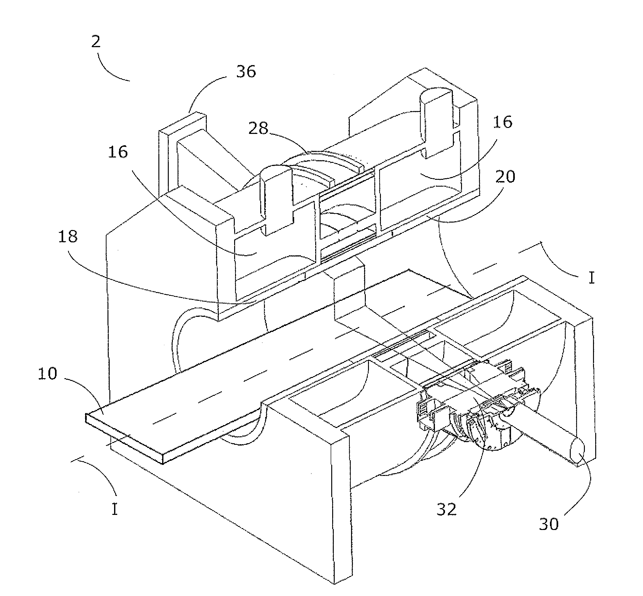
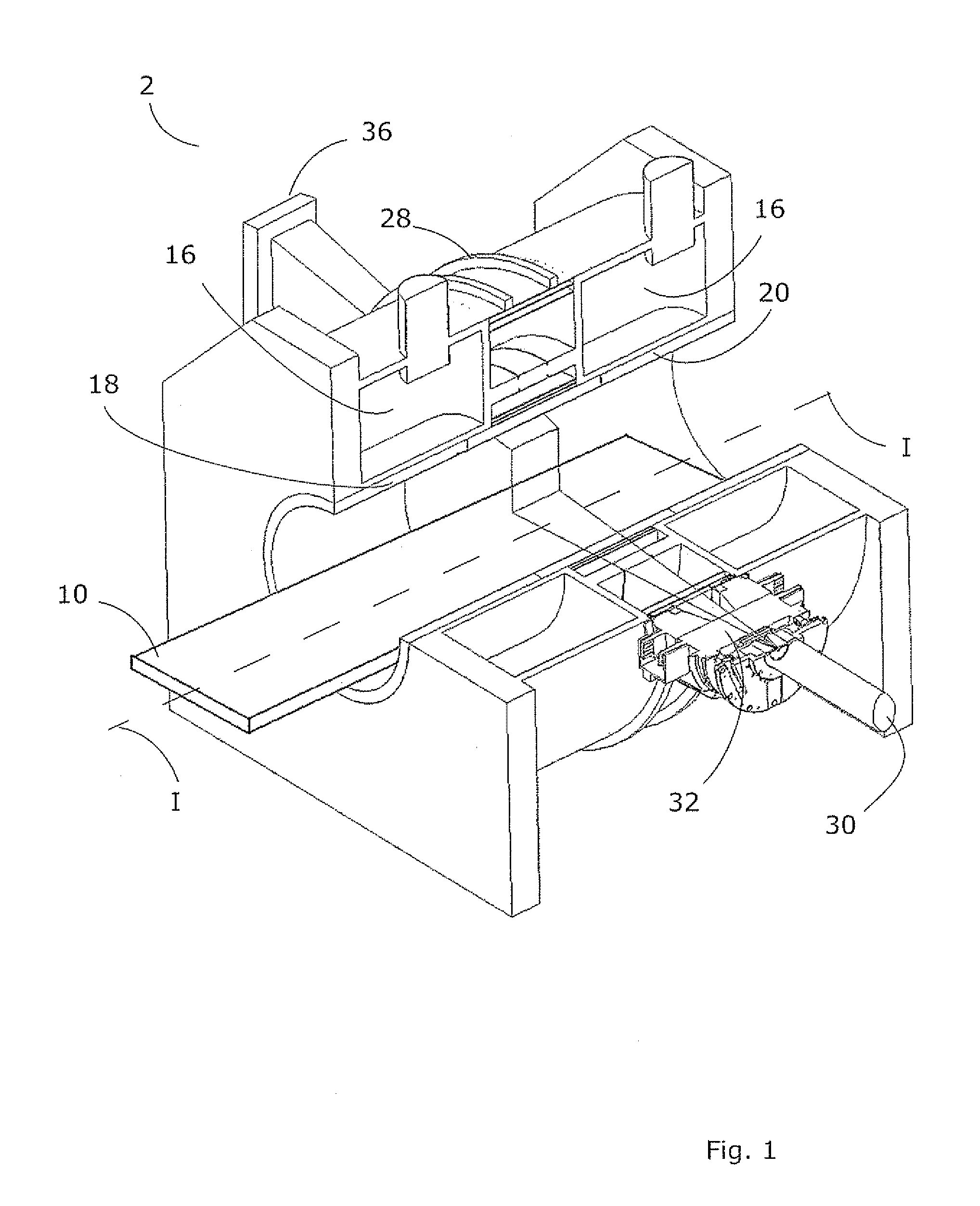
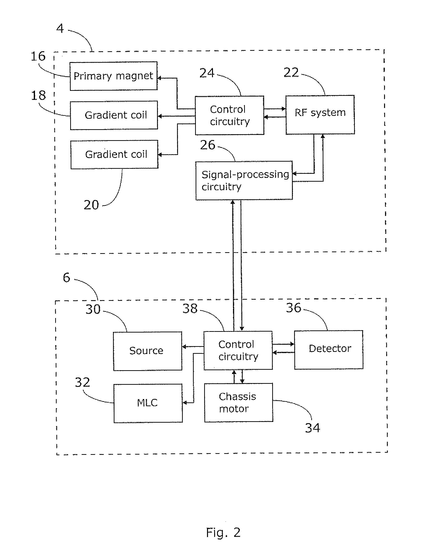
[0029]FIG. 1 shows a system according to embodiments of the present invention, comprising a radiotherapy apparatus and a magnetic resonance imaging (MRI) apparatus. The radiotherapy apparatus 6 and MRI apparatus 4 are shown schematically in FIG. 2.

[0030]The system includes a couch 10, for supporting a patient in the apparatus. The couch 10 is movable along a horizontal, translation axis (labelled “I”), such that a patient resting on the couch is moved into the radiotherapy and MRI apparatus. In one embodiment, the couch 10 is rotatable around a central vertical axis of rotation, transverse to the translation axis, although this is not illustrated. The couch 10 may form a cantilever section that projects away from a support structure (not illustrated). In one embodiment, the couch 10 is moved along the translation axis relative to the support structure in order to form the cantilever section, i.e. the cantilever section increases in length as the couch is moved and the lift remains s...


PUM


Abstract

Radiotherapy apparatus comprises a source of radiation mounted on a chassis, the chassis being rotatable about a rotation axis and the source being adapted to emit a beam of radiation along a beam axis that intersects with the rotation axis; a patient support, moveable along a translation axis; a set of magnetic coils located on either side of the beam, for establishing a magnetic field at the point of intersection, spaced from that point along a first direction; the translation axis, the rotation axis, and the first direction being substantially parallel; and further comprising a multi-leaf collimator fixed in its orientation with respect to the source of radiation, the multi-leaf collimator comprising a plurality of elongate leaves disposed with their longitudinal directions substantially aligned with the first direction and movable in that direction between a withdrawn position in which the leaf lies outside the beam, an extended position in which the leaf projects across the beam and a plurality of intermediate positions therebetween.

Description

FIELD OF THE INVENTION[0001]The present invention relates to a radiotherapy apparatus and, especially, to a form of multi-leaf collimator suited to certain types of radiotherapy apparatus with imaging devices.BACKGROUND ART[0002]It is known that exposure of human or animal tissue to ionising radiation will kill the cells thus exposed. This finds application in the treatment of pathological cells, for example. In order to treat tumours deep within the body of the patient, the radiation must however penetrate the healthy tissue in order to irradiate and destroy the pathological cells. In conventional radiation therapy, large volumes of healthy tissue can thus be exposed to harmful doses of radiation, resulting in prolonged recovery periods for the patient. It is, therefore, desirable to design a device for treating a patient with ionising radiation and treatment protocols so as to expose the pathological tissue to a dose of radiation which will result in the death of those cells, whil...

Claims


Application Information

Patent Timeline
IPC IPC(8): A61B5/055A61N5/00G21K5/08
CPCA61N5/1042A61N2005/1055A61N2005/1054A61N5/1045A61N5/1049A61N5/1081
Inventor ALLEN, JOHNBOURNE, DUNCAN NEILBROWN, KEVIN JOHN
Owner ELEKTA AB
Why Eureka
Try Eureka