Air/fuel ratio control apparatus for general-purpose engine

a technology of air/fuel ratio and control apparatus, which is applied in the direction of electrical control, process and machine control, instruments, etc., can solve the problems of engine not being properly started and engine not being also started

Active Publication Date: 2011-08-18
HONDA MOTOR CO LTD
View PDF26 Cites 9 Cited by
  • Summary
  • Abstract
  • Description
  • Claims
  • Application Information

AI Technical Summary

Benefits of technology

[0008]An object of this invention is therefore to overcome the foregoing problem by providing an air / fuel ratio control apparatus for a general-purpose engine that can select an appropriate one from among sets of fuel injection amount characteristics such that the engine can be properly started in various environments.

Problems solved by technology

As a result, when, for example, the alcohol rate is high, since the appropriate set of fuel injection amount characteristics is not selected appropriately before the engine start, the engine can not be properly started.
Further, as to an engine mounted on a generator or snowplow, if an appropriate one from among sets of fuel injection amount characteristics is not selected in response to a temperature and altitude of a place of use, the engine can not also be started.

Method used


Image

  • Air/fuel ratio control apparatus for general-purpose engine
  • Air/fuel ratio control apparatus for general-purpose engine
  • Air/fuel ratio control apparatus for general-purpose engine

Examples


first embodiment

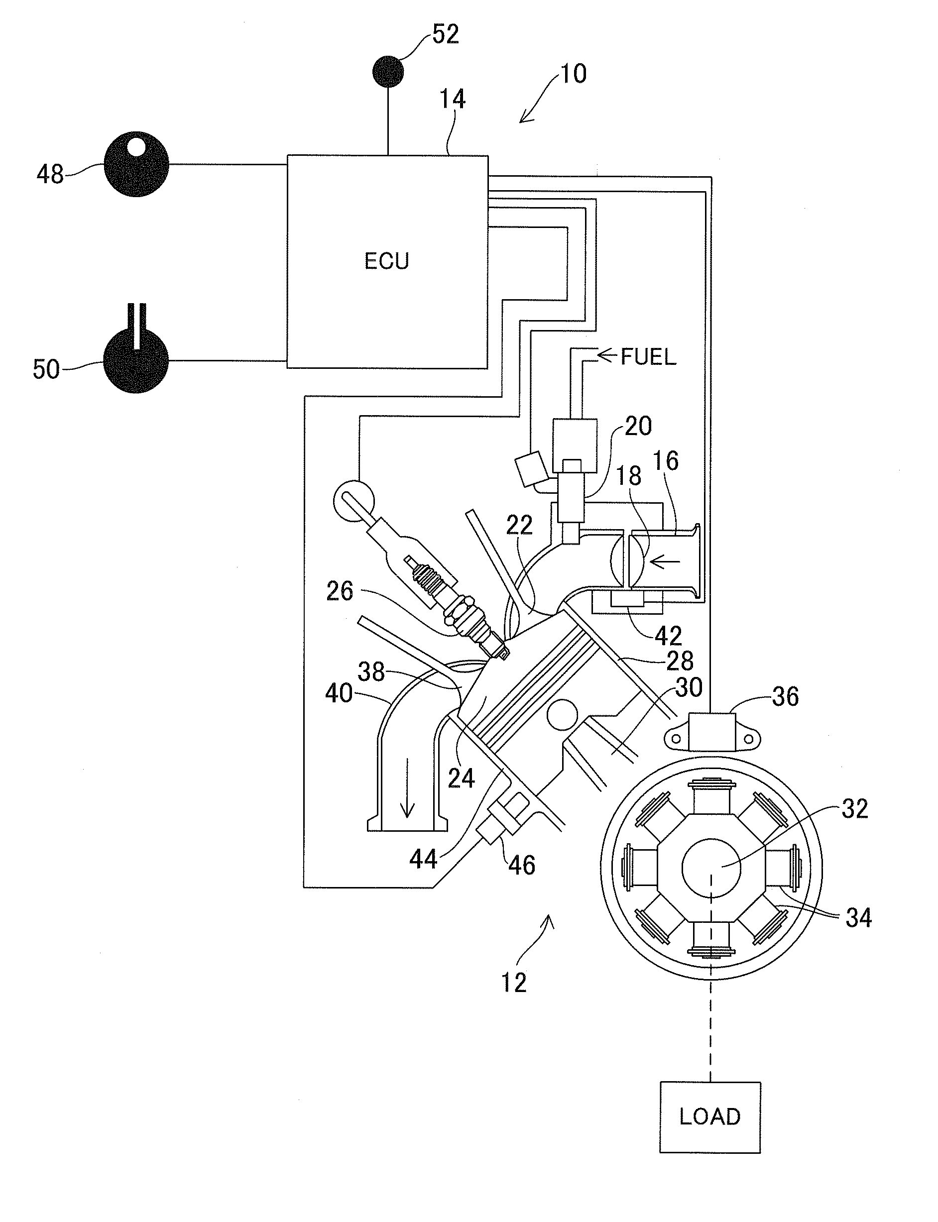
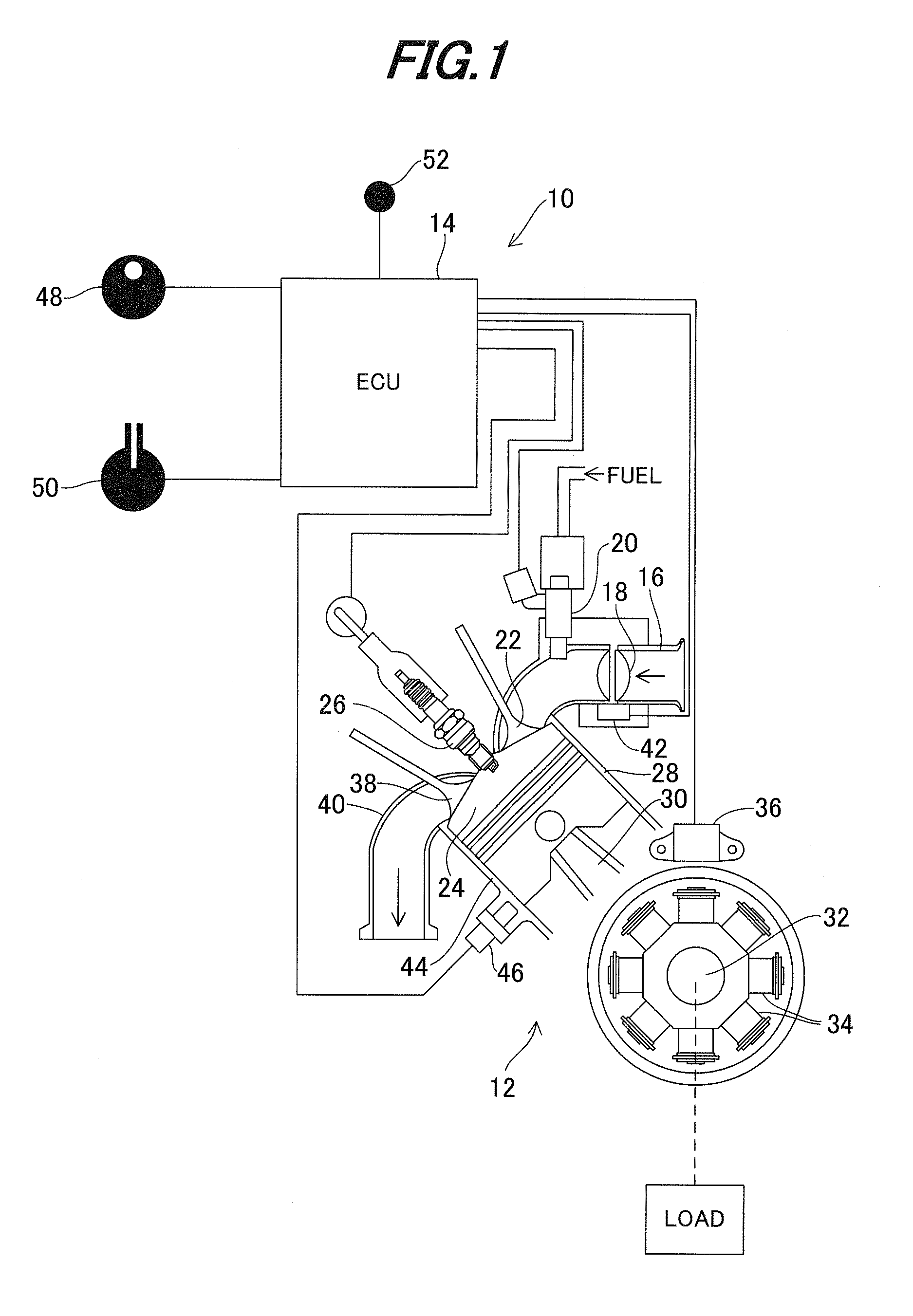
[0026]FIG. 1 is an overall schematic view showing an air / fuel ratio control apparatus for a general-purpose engine according to this invention.

[0027]In FIG. 1, symbol 10 designates the air / fuel ratio control apparatus for a general-purpose engine 12 (shown in cross-section) 12. The apparatus 10 has an Electronic Control Unit (ECU) 14 for electronically controlling the engine 12. The ECU 14 comprises a microcomputer having a CPU, memory (EEPROM or non-volatile memory) and other components.

[0028]The engine 12 is a single-cylinder, four-cycle, air-cooled, OHV engine with a displacement of, for example, 440 cc, and is a general-purpose engine to be mounted on a machine such as a generator, lawnmower and snowplow which functions as a load when connected to the engine 12.

[0029]An air intake pipe 16 of the engine 12 is installed with a throttle valve 18 and injector 20. Intake air sucked in and flowing in the air intake pipe 16 is regulated through the throttle valve 18 and fuel injected f...

second embodiment

[0099]FIG. 11 is an overall schematic view similar to FIG. 1, but showing an air / fuel ratio control apparatus for a general-purpose engine according to this invention.

[0100]Compared to the first embodiment, in the second embodiment, more number of fuel injection amount maps are prepared for, in addition to the alcohol rate of the mixed fuel, a temperature (i.e., air temperature) and altitude of a place where the engine 12 is situated and, in order to switch one from among the fuel injection amount maps, a mode selecting knob (switch) 54 is added and the map switching knob 50 is modified.

[0101]FIG. 12 is a view showing details of the mode selecting knob 54 and FIG. 13 is a view showing details of the map switching knob 50.

[0102]The mode selecting knob 54 is made turnable to switch the mode to select one from among an alcohol rate mode, air temperature mode and altitude mode. The mode selecting knob 54 is installed also to be manipulated by the operator.

[0103]The map switching knob 50...


PUM


Abstract

In an apparatus for controlling an air / fuel ratio of a general-purpose internal combustion engine using mixed fuel containing alcohol and gasoline and operated at a desired engine speed inputted by the operator while a throttle opening is regulated such that a detected engine speed converges to the inputted desired engine speed, a fuel injection amount determined for mixed fuel based on fuel injection amount characteristics is increased / decreased when a load is kept constant and the output air / fuel ratio is estimated to correct the fuel injection amount by the estimated air / fuel ratio, while a switch (knob) is installed to be manipulated by the operator to switch the fuel injection amount characteristics.

Description

BACKGROUND OF THE INVENTION[0001]1. Field of the Invention[0002]This invention relates to an air / fuel ratio control apparatus for a general-purpose internal combustion engine, particularly to an air / fuel ratio control apparatus for a general-purpose engine using mixed fuel containing alcohol and gasoline.[0003]2. Description of the Related Art[0004]Conventionally, there is proposed a technique for an engine using mixed fuel containing alcohol and gasoline, which is configured to provide an air / fuel ratio sensor (O2 sensor (oxygen sensor) or a wide-range air / fuel ratio sensor in the exhaust system to detect an air / fuel ratio to determine a deviation from a predetermined value caused due to the mixed alcohol, estimate a rate of the alcohol in the fuel based on the detected deviation of the air / fuel ratio, and determine a fuel injection amount based on one from among sets of characteristics (maps; mapped data) selected from the estimated alcohol rate (or correct the fuel injection amou...

Claims


Application Information

Patent Timeline
Patent Type & Authority Applications(United States)
IPC IPC(8): F02D41/04
CPCF02D19/0631F02D19/084F02D41/0025F02D41/1458F02D19/0613F02D2200/604Y02T10/36F02D19/061F02D19/088F02D2200/0404Y02T10/30F02D19/0655F02D19/081F02D41/0035F02D41/0052F02D41/182
Inventor FUKUSHIMA, TOMOKIYONEYAMA, TADAYUKIMATSUDA, HAYATOHASHIZUME, TAKASHI
Owner HONDA MOTOR CO LTD
Why Eureka
Try Eureka