Particle beam therapy system

Inactive Publication Date: 2011-08-25
MITSUBISHI ELECTRIC CORP
View PDF5 Cites 23 Cited by
  • Summary
  • Abstract
  • Description
  • Claims
  • Application Information

AI Technical Summary

Benefits of technology

[0014]Advantageous Effect Of The Invention
[0015]According to a particle beam therapy system of the present invention, light from a light source is made to be reflected by a light source mirror and to pass through a variable collimator, an irradiation field shape shaped by the variable collimator is projected on a photographing screen by the light passed through the variable collimator, a projection portion of the photographing screen is photographed by a photograp

Problems solved by technology

Therefore, the patient's body surface is not horizontal and is a body surface having a complicated curved surface; and thus, it becomes difficult to confirm a set shape of the variable collimator with good accuracy.
Therefore, the upper surface of the variable collimator is diffusely reflected by the light from the mirror; a planar surface portion, a collimator edge, and end portions of the variable collimator are blur; and

Method used


Image

  • Particle beam therapy system
  • Particle beam therapy system
  • Particle beam therapy system

Examples


Example

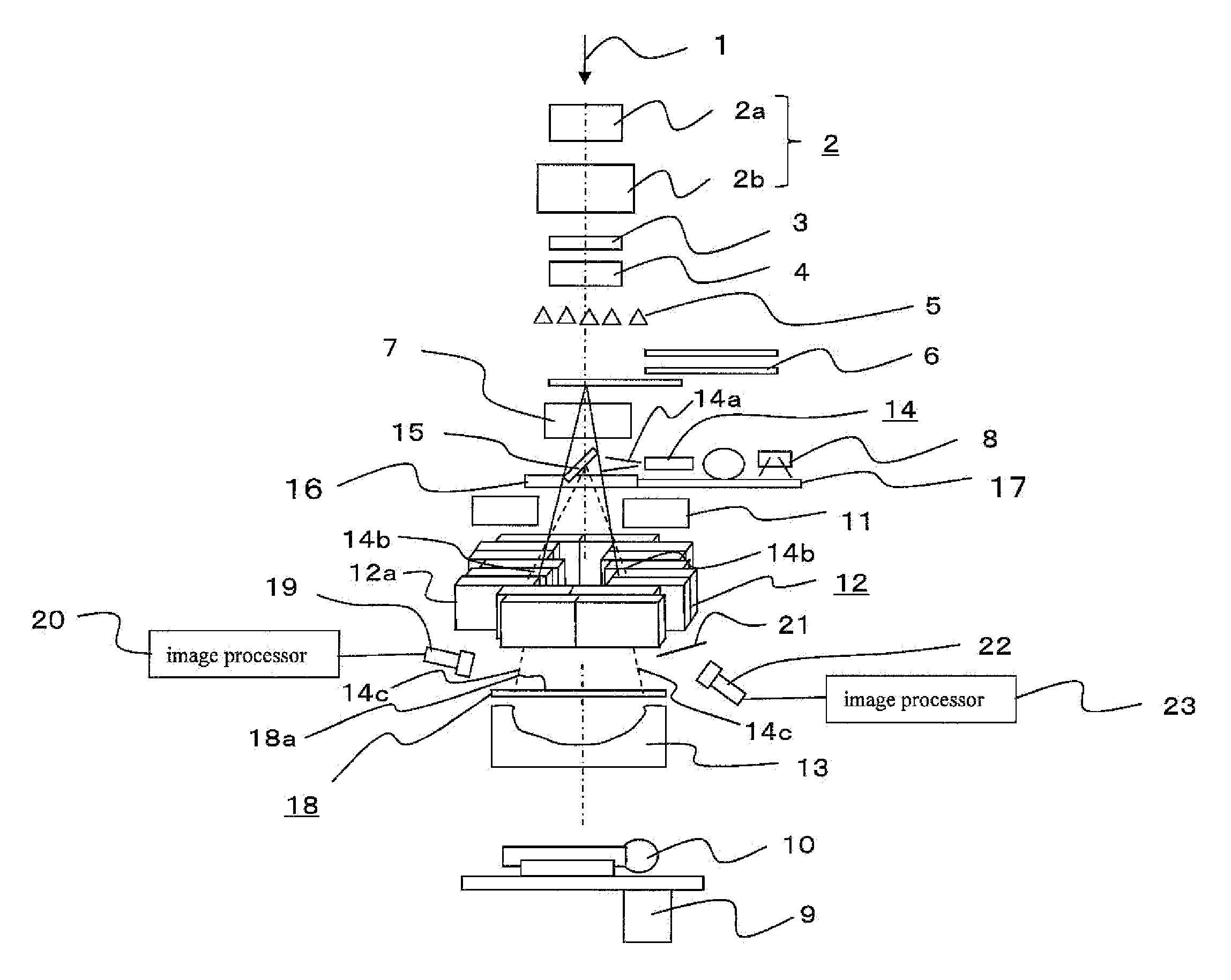
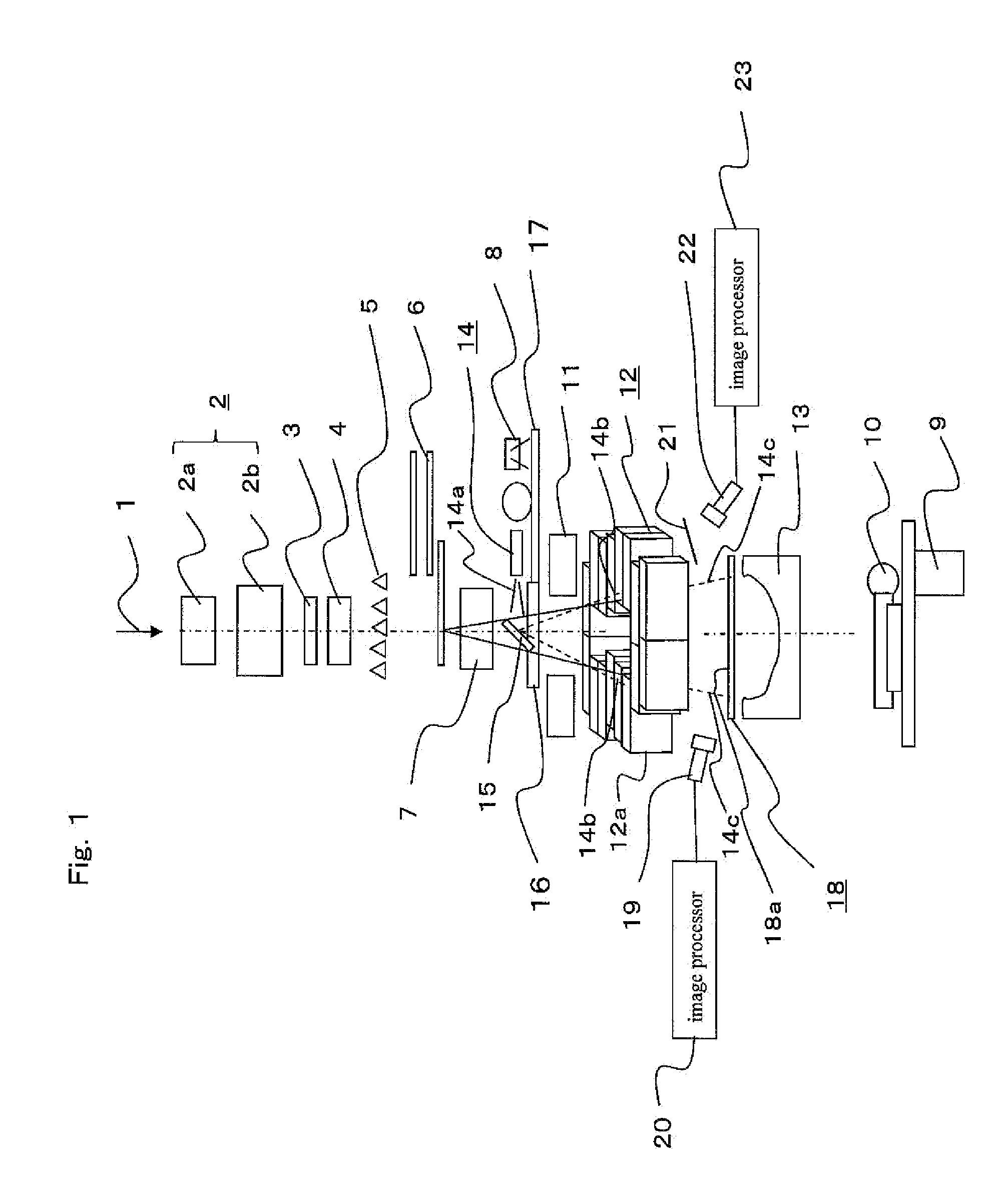
[0024]A particle beam therapy system according to Embodiment 1 of the present invention will be described with reference to a schematic configuration diagram shown in FIG. 1. Incidentally, a variable collimator 12 is shown as a perspective view. In FIG. 1, reference numeral 1 denotes a particle beam of carbon, proton or the like transported from an accelerator (not shown in the drawing), and the particle beam proceeds in an irradiation axis direction. 2 denotes electromagnets which are composed of a pair of electromagnets 2a and 2b and scan a path or trajectory of the particle beam 1 transported from the accelerator. 3 denotes a scatterer which diffuses the particle beam 1 passed through the electromagnets 2; 4 denotes a dose monitor by which an irradiation dose of the particle beam 1 passed through the scatterer 3 is measured; 5 denotes a ridge filter (or energy modulation means) in which an energy spectrum (dose distribution) in a depth direction is adjusted by the thickness of a ...

Example

Embodiment 2

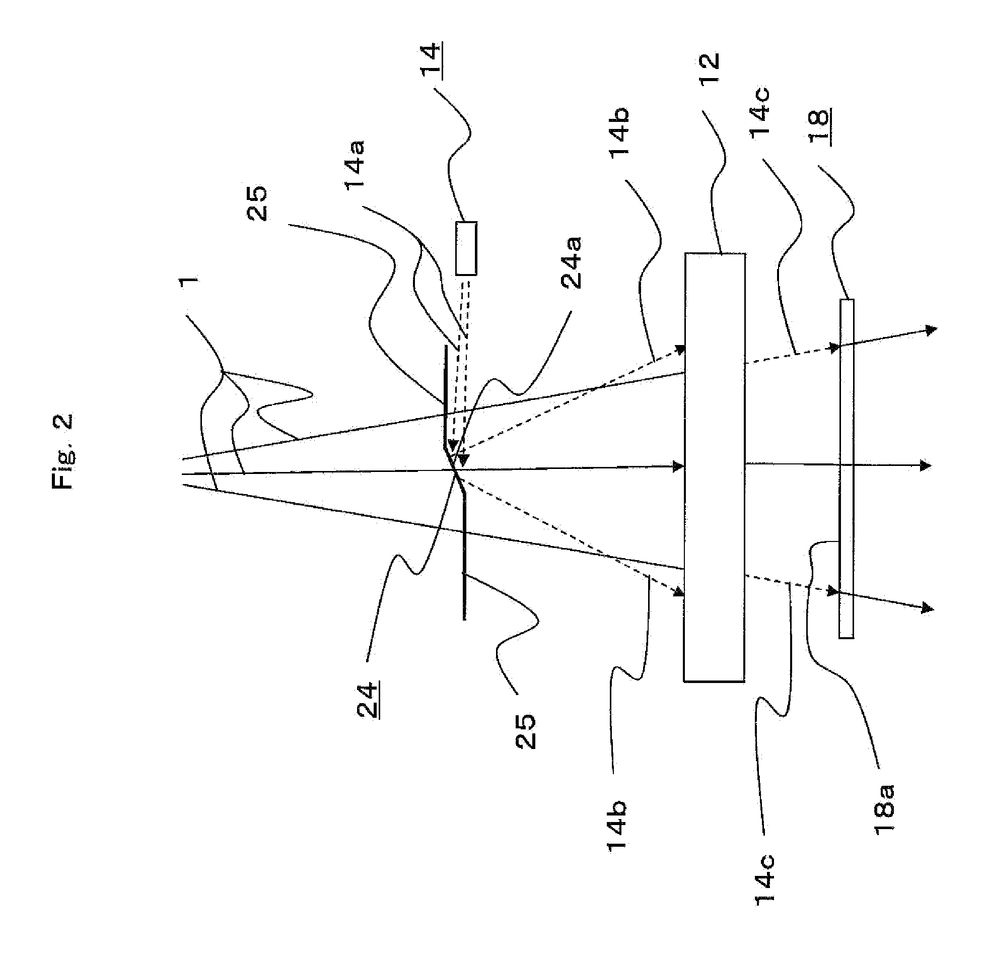
[0034]A relevant part of a particle beam therapy system according to Embodiment 2 of the present invention will be described with reference to a schematic configuration diagram shown in FIG. 2. In FIG. 2, reference numerals 1, 12, 14, 14a, 14b, 14c, 18, and 18a are the same as the configuration of the aforementioned Embodiment 1. 24 denotes a light source mirror which is arranged on a path or trajectory of the particle beam 1 on the upstream side of the variable collimator 12, and in which light from the light source 14 is made to be reflected at a reflecting section 24a and to pass through the variable collimator 12. The light from the light source 14 is emitted from a substantially transverse direction; and therefore, the light source mirror 24 is inclined at approximately 45 degrees to make the light from the light source 14 reflect to the variable collimator 12 side at the reflecting section 24a of the light source mirror 24. Incidentally, the light source mirror 24 ...

Example

Embodiment 3

[0038]As is apparent from FIG. 2, a particle beam therapy system according to Embodiment 3 of the present invention is characterized in that a light source mirror 24 is arranged in an irradiation region of a particle beam 1. Consequently, as described in the mirror of the aforementioned background art, the mirror is not required to be extended until outside the range of the irradiation region of the particle beam 1 and the length occupied in the irradiation axis direction of the particle beam 1 is not also required to be large, being several tens cm, and the light source mirror 24 may only make the light from the light source 14 reflect; and therefore, the light source mirror 24 can be arranged in the irradiation region of the particle beam 1. As a result, the light source mirror 24 can be reduced in size and the length occupied in the irradiation axis direction of the particle beam 1, that is, height can also be reduced. The height of the light source mirror 24 may be s...


PUM


Abstract

Light from a light source is made to be reflected by a light source mirror and to pass through a variable collimator, an irradiation field shape shaped by the variable collimator is projected on a photographing screen by the light passed through the variable collimator, a projection portion of the photographing screen is photographed by a photographic device, and an image photographed by the photographic device is analyzed by an image processor.

Description

TECHNICAL FIELD[0001]The present invention relates to a particle beam therapy system which is intended for the treatment of cancer, malignant tumor or the like and irradiates to treat a patient's diseased part with a particle beam of carbon, proton or the like.BACKGROUND ART[0002]For the treatment of patient's cancer, malignant tumor or the like, an irradiation region of a particle beam is required to be conformed to the shape of a patient's diseased part in order to irradiate to treat the diseased part with a proper dose of the particle beam. To that end, it is important that the shape of a variable collimator composed of a plurality of leaves is properly set, and in addition, that the distribution of both an irradiation dose in a transverse direction and an irradiation dose in a depth direction is homogenized so as to irradiate the whole diseased part with a homogeneous dose. More particularly, it becomes important to confirm the shape of the variable collimator in order to make t...

Claims


Application Information

Patent Timeline
IPC IPC(8): A61N5/10
CPCA61N5/1048A61N2005/1087A61N2005/1056A61N5/10A61B6/00
Inventor PU, YUEHUOTANI, TOSHIHIRO
Owner MITSUBISHI ELECTRIC CORP
Why Eureka
Try Eureka