Motor controller and electric power steering device

a technology of motor controller and electric steering device, which is applied in the direction of emergency protective arrangements for limiting excess voltage/current, instruments, pulse techniques, etc., to achieve the effect of reducing device size, improving reliability, and reducing costs

Inactive Publication Date: 2011-08-25
JTEKT CORP
View PDF6 Cites 23 Cited by
  • Summary
  • Abstract
  • Description
  • Claims
  • Application Information

AI Technical Summary

Benefits of technology

[0007]Replacement of mechanical relays by semiconductor switching elements such as FETs in power supply breakers of motor controllers for, for example, electric power steering devices is now promoted in order to improve reliability, reduce the size of devices, or decrease costs. However, since a semiconductor switching element includes a parasitic diode, a power supply breaker using such semiconductor switching elements mus...

Problems solved by technology

A problem is detected (determined) in the power supply relay typically by monitoring ...

Method used


Image

  • Motor controller and electric power steering device
  • Motor controller and electric power steering device
  • Motor controller and electric power steering device

Examples


Embodiment Construction

[0018]One embodiment of the present invention will now be described with reference to FIGS. 1 to 3.

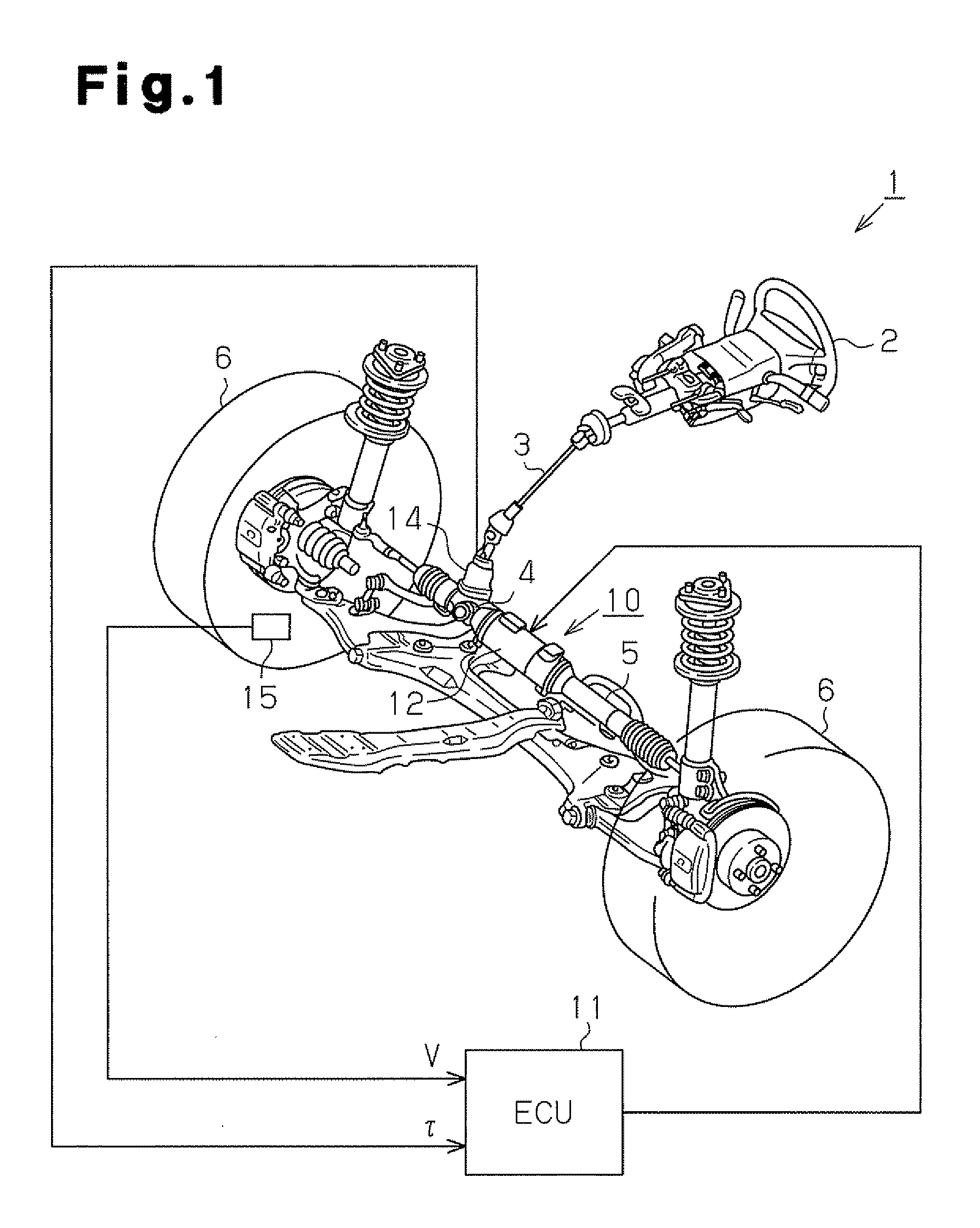
[0019]As illustrated in FIG. 1, in a vehicle having an electric power steering (EPS) device 1 according to the present embodiment, a steering shaft 3 extending from a steering wheel 2 is connected to a rack 5 through a rack and pinion mechanism 4. As the driver manipulates the steering wheel 2, the steering shaft 3 rotates. Rotation of the steering shaft 3 is converted into linear reciprocation of the rack 5 through the rack and pinion mechanism 4 and thereby changes the steering angle of steerable wheels 6.

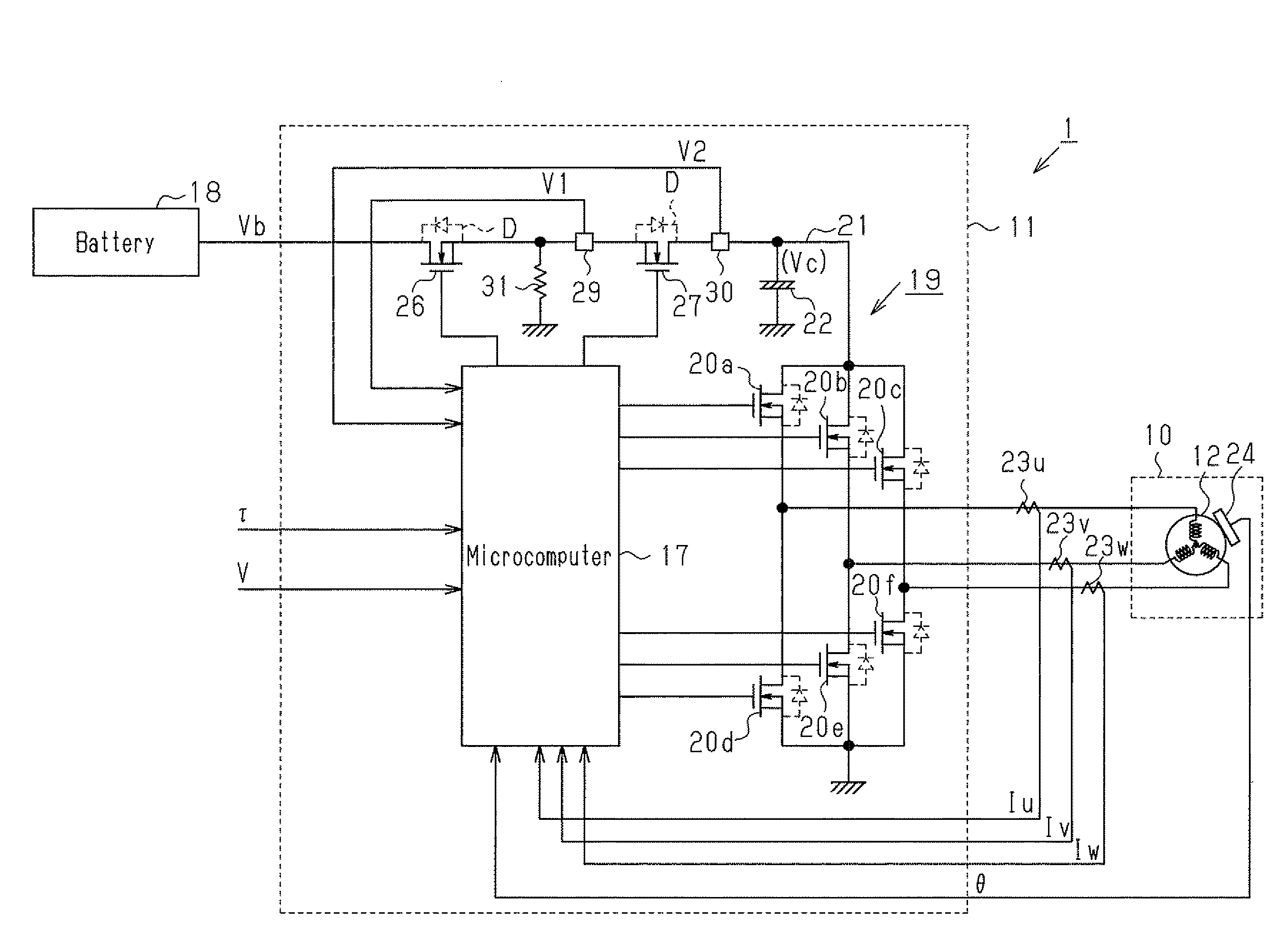
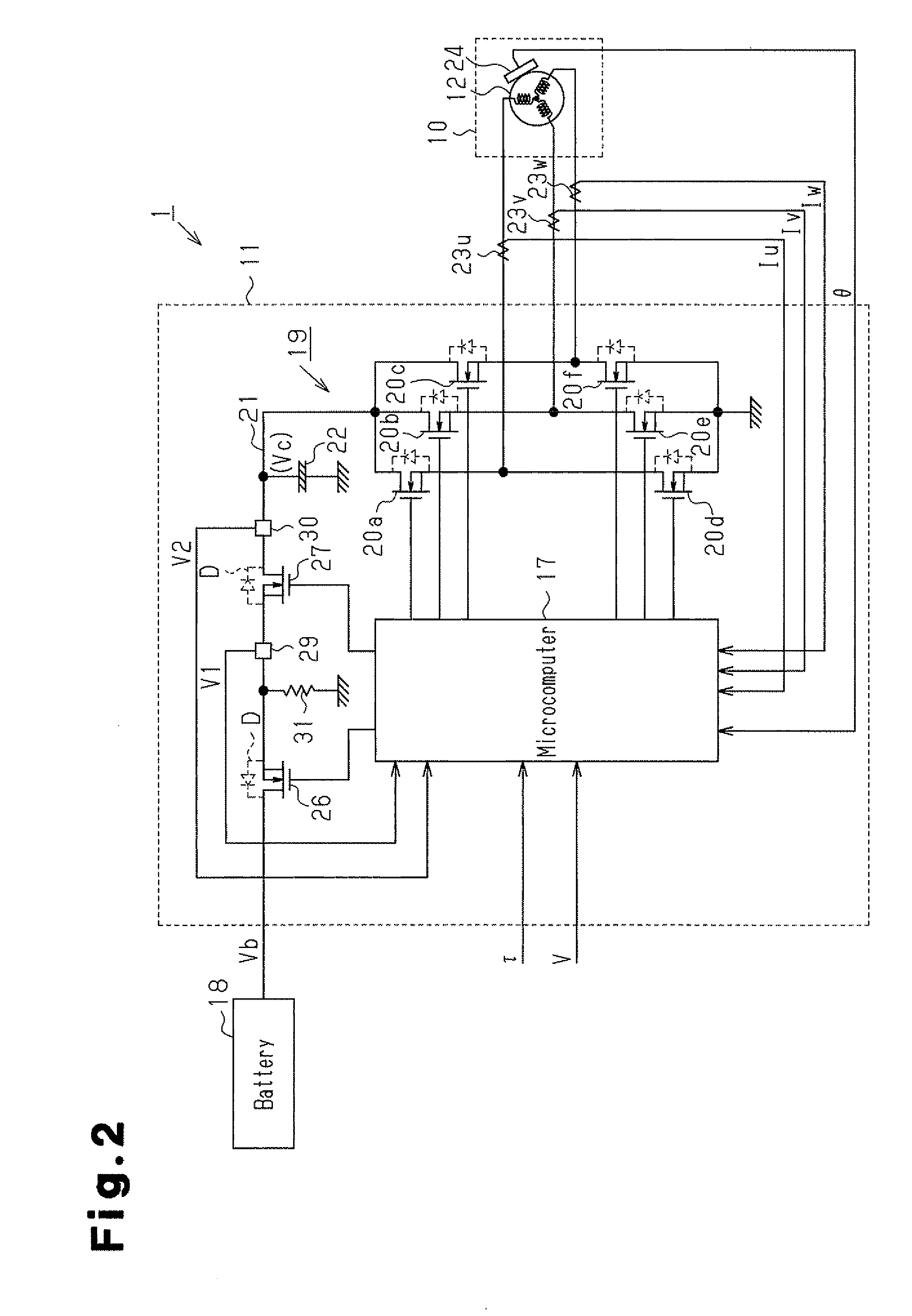
[0020]The EPS device 1 includes, an EPS actuator 10 and an ECU 11. The EPS actuator 10 serves as a steering force assist device that applies assist force to the steering system of the vehicle to assist in manipulation of the steering wheel 2 by the driver. The ECU 11 serves as control means (a control section) that controls operation of the EPS actuator 10.

[0021]The EPS actuator 10 ...


PUM


Abstract

A microcomputer detects and determines whether a problem exists in a power supply breaker of an ECU functioning as a motor controller. Specifically, the microcomputer determines whether there is a malfunction caused by a short circuit in a first FET based on the output voltage and output voltage that are detected in a first FET and a second FET, respectively, when the switching states of the first and second FETs are both off. Afterwards, the microcomputer determines whether there is a malfunction caused by a break in the first FET based on the output voltages of the first and second FETs that are detected when only the first FET is switched on. If the microcomputer determines that the first FET is free from any malfunction, the microcomputer determines whether there is a malfunction caused by a short circuit or a break in the second FET by comparing the output voltage of the first FET and a charge voltage of a smoothing capacitor that are detected afterwards.

Description

TECHNICAL FIELD[0001]The present invention relates to a motor controller and an electric power steering device.BACKGROUND ART[0002]Many motor controllers include a power supply breaker (power supply breaking means) that is arranged in a power supply line connecting a power supply to a driver circuit and interrupts the power supply line. A conventional power supply breaker is configured by a relay circuit, or, in other words, a power supply relay, which uses a mechanical relay in which a contact is selectively turned on and off by supply of the power to a coil mounted in the power supply breaker (see, for example, Patent Document 1). A problem is detected (determined) in the power supply relay typically by monitoring change in the output voltage from the power supply relay when the power supply is turned on.[0003]Specifically, in a motor controller 46 illustrated in FIG. 4, for example, a motor 42 receives drive power based on power supply voltage Vb from a driver circuit 43. A power...

Claims


Application Information

Patent Timeline
IPC IPC(8): H02H9/00B62D6/00B62D5/04B62D101/00B62D119/00H02P29/00H02P29/40
CPCB62D5/0487G01R31/3277H02P29/022H02P29/032H03K17/6874
Inventor SAKAI, ATSUO
Owner JTEKT CORP
Why Eureka
Try Eureka