Multicore optical fiber

a multi-core, optical fiber technology, applied in the direction of optical fibres with multi-layer cores/claddings, optical waveguide light guides, instruments, etc., can solve the problems of increasing the dispersion of polarization modes, and affecting the performance of optical fibers, so as to reduce the mode coupling, reduce the crosstalk effectively, and reduce the effect of mode coupling

Active Publication Date: 2011-08-25
SUMITOMO ELECTRIC IND LTD
View PDF2 Cites 25 Cited by
  • Summary
  • Abstract
  • Description
  • Claims
  • Application Information

AI Technical Summary

Benefits of technology

[0012]Preferably, in the multicore optical fiber according to the present invention, at least one pair of adjacent multicore units among the plurality of multicore units have the same core arrangement structure. In addition, it is also preferable that a core region included in one of the adjacent multicore units and a core region included in the other of the adjacent multicore units have refractive index distributions different from each other. This can reduce the mode coupling between the adjacent multicore units including the refractive index distributions different from each other, thereby effectively suppressing the crosstalk between the multicore uni

Problems solved by technology

Therefore, in such a conventional multicore fiber, a large structural birefringence may occur, thereby increasing polarization mode dispersion (PMD).
Since the polarization mode dispersion is one of factors restricting the bit ra

Method used


Image

  • Multicore optical fiber
  • Multicore optical fiber
  • Multicore optical fiber

Examples


first embodiment

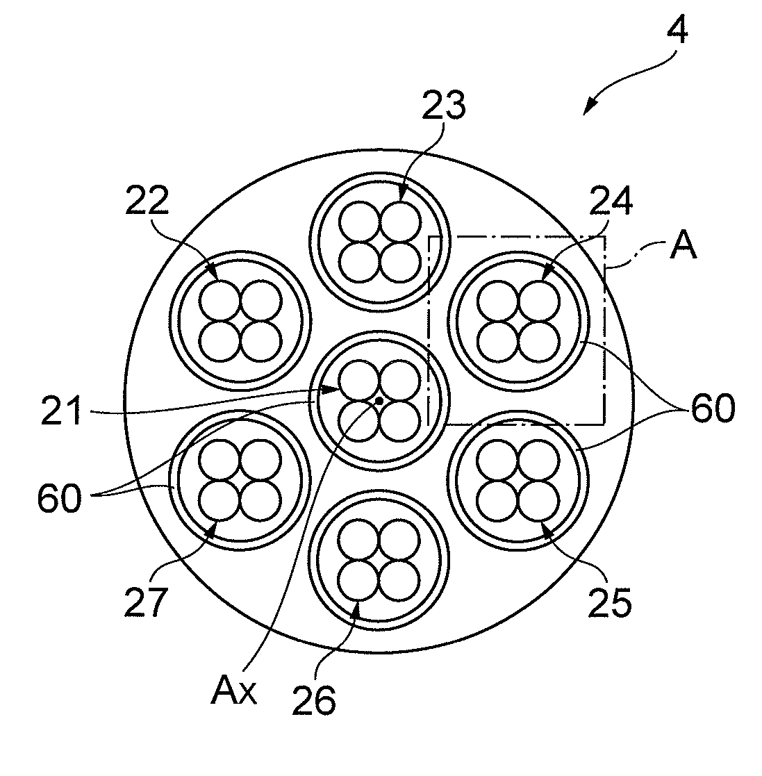
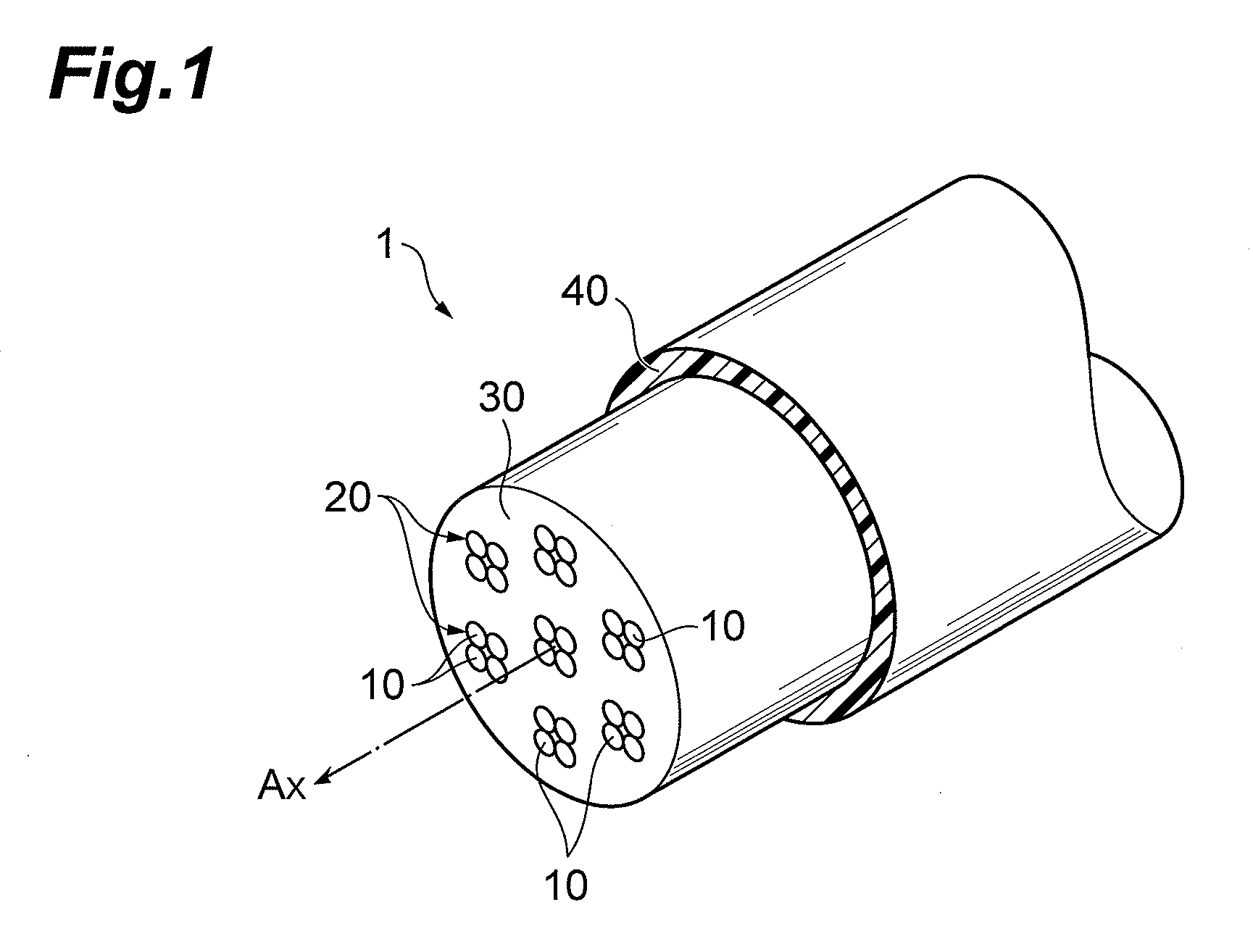
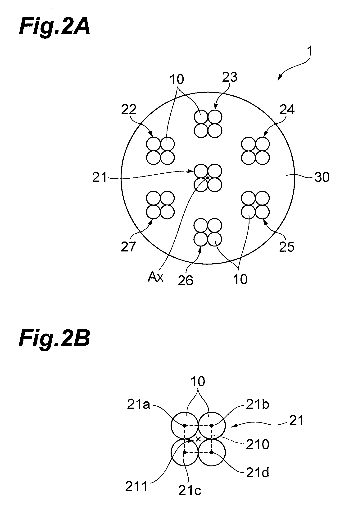
[0022]FIG. 1 is a view showing the structure of the first embodiment of the multicore optical fiber according to the present invention. As shown in FIG. 1, the multicore optical fiber 1 comprises a bare optical fiber including a plurality of multicore units each extending along an optical axis AX coinciding with the center of the multicore optical fiber 1 while being covered with a cladding region 30 thereabout and a resin coating 40 disposed at the outer periphery of the bare optical fiber. Each of the plurality of multicore units 20 has a plurality of core regions 10 arranged such as to construct a predetermined core arrangement structure on a cross section of the multicore optical fiber 1 orthogonal to the optical axis AX. In the first embodiment, each multicore unit 20 is constituted by four core regions 10. A common cladding region may integrally cover the core regions 10, or cladding regions may be prepared for the respective core regions 10.

[0023]FIGS. 2A and 2B show the cros...

second embodiment

[0026]FIGS. 3A and 3B are views showing a cross-sectional structure in the second embodiment of the multicore optical fiber according to the present invention, in which FIG. 3A depicts only the bare optical fiber part excluding the resin coating. The cross section of FIG. 3A coincides with the cross section orthogonal to the optical axis in the multicore optical fiber 1 according to the first embodiment shown in FIG. 1.

[0027]The multicore optical fiber 2 according to the second embodiment shown in FIG. 3A differs from the multicore optical fiber 1 according to the first embodiment in the following points. Each of multicore units 31 to 37 included in the multicore optical fiber 2 is constituted by seven core regions 10 (10a to 10d). At least one pair of adjacent multicore units among the multicore units 31 to 37 have the same core arrangement structure (the arrangement of core regions included in each multicore unit defined on the cross section of FIG. 3A). The refractive index distr...

third embodiment

[0035]FIGS. 4A and 4B are views showing a cross-sectional structure in the third embodiment of the multicore optical fiber according to the present invention, in which FIG. 4A depicts only the bare optical fiber part excluding the resin coating. The cross section of FIG. 4A coincides with the cross section orthogonal to the optical axis in the multicore optical fiber 1 according to the first embodiment shown in FIG. 1.

[0036]The multicore optical fiber 3 according to the third embodiment shown in FIG. 4A differs from the multicore optical fiber 1 according to the first embodiment in the following point. That is, the multicore units 41 to 47 included in the multicore optical fiber 3 according to the third embodiment have core arrangement structures different from each other.

[0037]As shown in FIG. 4A, the multicore optical fiber 3 according to the third embodiment is provided with seven multicore units 41 to 47 having their centers located at lattice points of a hexagonal lattice. In p...


PUM


Abstract

The present invention relates to a multicore optical fiber having a structure for effectively inhibiting polarization mode dispersion from increasing, and the multicore optical fiber comprises a plurality of multicore units and a cladding region integrally covering the plurality of multicore units while separating the multicore units from each other. Each of the plurality of multicore units includes a plurality of core regions arranged such as to construct a predetermined core arrangement structure on a cross section orthogonal to an axis. The core arrangement structure of each multicore unit on the cross section has such a rotational symmetry as to coincide with the unrotated core arrangement structure at least three times while rotating by 360° about a center of the multicore unit, thereby reducing the structural asymmetry of each multicore unit. This lowers the structural birefringence in each multicore unit, thereby inhibiting the polarization mode dispersion from increasing in the multicore optical fiber.

Description

BACKGROUND OF THE INVENTION[0001]1. Field of the Invention[0002]The present invention relates to a multicore optical fiber in which a plurality of core regions are arranged on the same cross section as a transmission medium for optical communications.[0003]2. Related Background Art[0004]As optical fiber networks have recently been increasing their traffic volume, attention has been focused on the use of multicore optical fibers (MCF) containing a number of cores within a cladding region. As an example of the multicore optical fibers, FIG. 7 of Y. KOKUBU and M. KOSHIBA, “Heterogeneous uncoupled and homogeneous coupled multicore fibers”, BS-7-7, IEICE2009, Sep. 15-Sep. 18, 2009) (Document 1) illustrates a multicore optical fiber in which a coupled core group constituted by densely arranging a plurality of cores having the same refractive index and the same core diameter is separated from its adjacent coupled core group by an uncoupled distance which can prevent crosstalk from occurrin...

Claims


Application Information

Patent Timeline
IPC IPC(8): G02B6/036
CPCG02B6/105G02B6/02042
Inventor SASAOKA, EISUKE
Owner SUMITOMO ELECTRIC IND LTD
Why Eureka
Try Eureka