Supercharge Your Innovation With Domain-Expert AI Agents!

Ultrasound probe

a technology of ultrasonic beam and probe, which is applied in the direction of sound producing devices, diagnostics, using reradiation, etc., can solve the problems of unsatisfactory solutions, interference and degradation of reflected signals, and the profile of said ultrasonic beam is not very homogeneous, so as to achieve a wide transmission band

Inactive Publication Date: 2011-08-25
ESAOTE
View PDF14 Cites 16 Cited by
  • Summary
  • Abstract
  • Description
  • Claims
  • Application Information

AI Technical Summary

Benefits of technology

[0016]Thus, advantageously, the one or more layers already provided within the probe are used, which match the acoustic impedance of tissues of the body under examination with the acoustic impedance of electroacoustic transducers, and therefore allow the energy to be transferred at the greatest extent between the electroacoustic transducers and tissues of the body under examination, thereby guaranteeing a greater sensitivity and bandwidth, for the ultrasonic beam to be apodized on the transverse plane such to concentrate the acoustic energy in a central area in the vicinity of the scan plane and to increase the difference in the acoustic energy between such central area and the peripheral areas farther from the scan plane.
[0041]Moreover, it is possible to have the two additional acoustic impedance matching layers used as resonator elements, with the advantage of obtaining a wider transmission band.

Problems solved by technology

This means that on the plane transverse to the scan plane neither the presence of side lobes in the ultrasonic beam nor the presence of an unshaped acoustic field in the near field can be avoided with electronic controls, and therefore the profile of said ultrasonic beam is not very homogeneous.
This substantial non-homogeneity leads to a signal response from reflectors arranged on the transverse plane in areas farther from the scan plane and this causes the reflected signal to be subjected to interferences and degradation.
However, those solutions do not provide satisfactory results, or results important enough to justify the related increase in complexity and manufacturing costs.

Method used


Image

  • Ultrasound probe
  • Ultrasound probe
  • Ultrasound probe

Examples


first embodiment

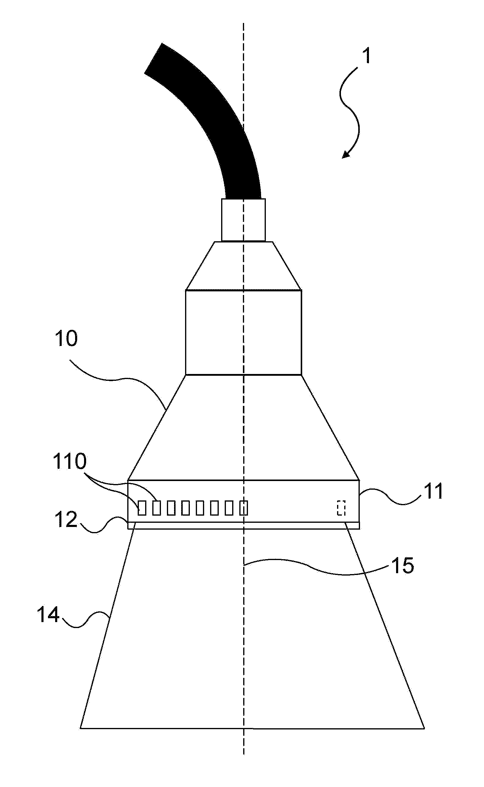
[0088]FIG. 9 shows a side view of the acoustic impedance matching layer according to the invention.

[0089]In this embodiment, the ultrasound probe is provided only with one acoustic impedance matching layer 12, which is an apodizing layer 120, and has a lower sound absorption in the central portion closer to the scan plane 14 and a greater sound absorption in the side areas farther from the scan plane 14.

[0090]The electroacoustic transducer array 11 on the pulse emitting / receiving face is overlapped by the apodizing layer 120 with a variable absorption depending on the distance from the center, while on the opposite face it has a high absorption backing layer 13 for damping pulses emitted in that direction.

second embodiment

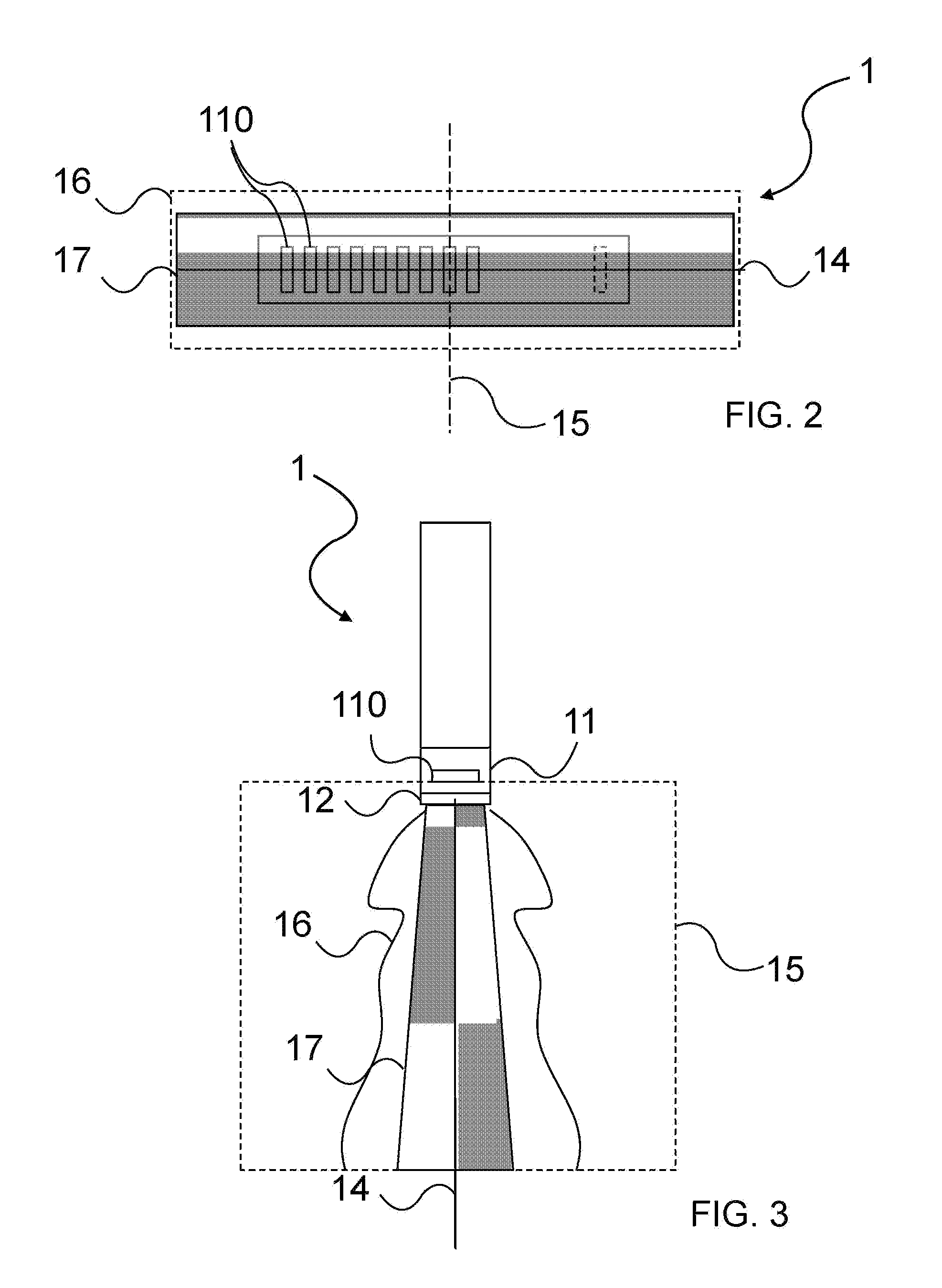
[0091]A second embodiment, shown in FIG. 10, provides for a further acoustic impedance matching layer overlapping the apodizing layer 120. The interface surface between the two layers has a concave shape, such that the apodizing layer 120 overlapping the electroacoustic transducer array 11 is thicker at the peripheral opposite parts of the electroacoustic transducers of said array 11 with respect to the scan plane 14 and is thinner at the central part of the electroacoustic transducers of said array 11.

[0092]In a further embodiment, at least one of the acoustic impedance matching layers is made of a material filled with glass and / or ceramic powder or the like.

[0093]In a preferred embodiment the apodizing layer 120 is made of a sound absorbing material.

[0094]On the contrary, the layer in contact with the body under examination is a focusing layer 121 and it is made of a non absorbing material.

[0095]The focusing layer 121 is made of a material having a propagation velocity slower than...


PUM


Abstract

An ultrasound probe for diagnostic images includes a set or array of electroacoustic transducers generating an ultrasonic beam and defining at least one scan plane or a predetermined scan volume, and one or more layers matching acoustic impedance characteristics of the transducers with acoustic impedance characteristics of tissues under examiantion. The layers overlap the transducers, on the face emitting / receiving acoustic pulses. Acoustic properties of the material or materials constituting the one or more layers, the geometric shape of the layers, and / or the structure of the transducers cause the ultrasonic beam to be apodized and the profile of the ultrasonic beam in a plane perpendicular to the scan plane and parallel to the ultrasonic beam to be highly homogeneous. The emitted pulse has a greater intensity uniformity in the part of the ultrasonic beam closer to the scan plane and a predetermined lower intensity in side lobes of the ultrasonic beam.

Description

FIELD OF THE INVENTION[0001]The present invention relates to an ultrasound probe for diagnostic images that includes a set or array of electroacoustic transducers configured to generate an ultrasonic beam to be introduced into a body under examination, the electroacoustic transducers being arranged such to define one or more scan planes.BACKGROUND OF THE INVENTION[0002]A type of ultrasound probes, generally called array probes, may be, for example, linear or convex phased array probes, and are widely used for diagnostic purposes in several technical fields and above all in the medical field.[0003]The major advantage of such probes is having a predetermined amount of electroacoustic transducers arranged side by side only along one line (linear probe) or along two or more lines (two-dimensional probe) such to generate an ultrasonic beam whose space features, called focusing, can be electronically controlled by timing the emission of each individual electroacoustic transducer of the ar...

Claims


Application Information

Patent Timeline
IPC IPC(8): A61B8/14
CPCG10K11/02G01S15/8909G01S15/8915
Inventor CEROFOLINI, MARINO
Owner ESAOTE
Features
  • R&D
  • Intellectual Property
  • Life Sciences
  • Materials
  • Tech Scout
  • Unparalleled Data Quality
  • Higher Quality Content
  • 60% Fewer Hallucinations
Learn More