Optical structure to reduce internal reflections

a technology of optical structure and internal reflection, applied in the field of optical structure, can solve the problems of increasing noise, affecting the performance of optical devices, and affecting the quality of optical devices, so as to reduce internal reflections, reduce noise, and reduce internal reflections of optical devices

Active Publication Date: 2012-08-28
UNIFIED INNOVATIVE TECH
View PDF22 Cites 0 Cited by
  • Summary
  • Abstract
  • Description
  • Claims
  • Application Information

AI Technical Summary

Benefits of technology

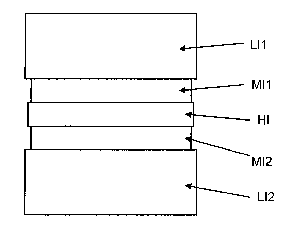
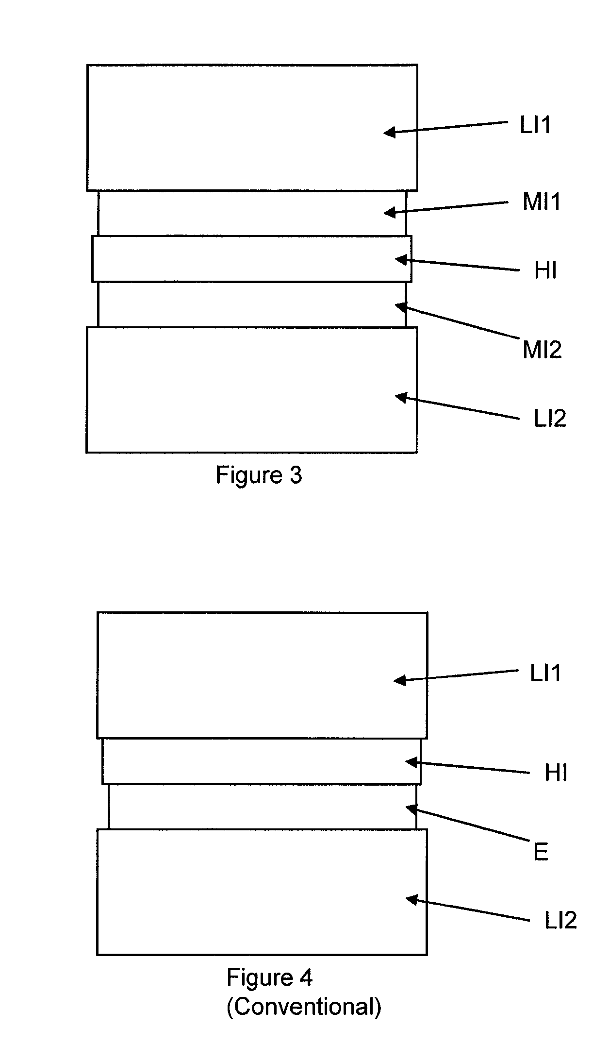
[0010]A device and method in accordance with the present invention can be used in an optical system, such as a liquid crystal display, to minimize internal reflections. More particularly, the device and method in accordance with the present invention provide a structure that includes a first layer formed between a second and third layer, wherein a refractive index of the first layer is greater than a refractive index of the second and third layers. Further, a fourth layer is formed on one side of the second layer, and a fifth layer is formed on one side of the third layer, wherein the fourth and fifth layers have a lower refractive index than the second and third layers, respectively. The device and method in accordance with the present invention reduce internal reflections of an optical device while utilizing fewer layers relative to conventional optical devices. Additionally, a display device, such as an LCD, employing principles in accordance with the present invention is less costly to produce relative to conventional LCD devices.
[0018]According to one aspect of the invention, the respective layers are optimized to minimize total reflectivity by destructive interference.
[0024]According to one aspect of the invention, a method for minimizing internal reflections in an optical device is provided, the optical device including a stack of layers, the stack comprising a first layer having a first refractive index, a second layer having a second refractive index, and a third layer having a third refractive index, the second layer formed between the first and third layer, wherein the second refractive index is numerically greater than the first refractive index and third refractive index, the method includes: forming a fourth layer having a fourth refractive index between the first and second layers, and forming a fifth layer having a fifth refractive index between the second and third layers, wherein the second refractive index is numerically greater than the fourth refractive index and the fifth refractive index, the fourth refractive index is numerically greater than the first refractive index, and the fifth refractive index is numerically greater than the third refractive index.
[0026]According to one aspect of the invention, the method includes optimizing the respective layers of the stack to minimize total reflectivity in the optical device by destructive interference.

Problems solved by technology

Many optical systems contain layers of contrasting refractive index, n. This gives rise to reflections within the system, diverting incident light from its designed path, decreasing efficiency and increasing noise.
In some such systems the higher-index medium is thin enough so that interference between reflections at the two surfaces of the higher-index layer can take place, constructively or destructively, depending on the optical path difference.
Reflection of ambient light at a display device undesirably reduces the contrast of the image seen by a viewer.
However, reflections arise within the device, particularly at the ITO electrodes and silicon nitride layers, which also contribute to the degradation of the image in a brightly lit room.
All of the layers, an outermost layer and the internal, light-emitting layers, have thicknesses chosen, according to their refractive index, to result in destructive interference of ambient light in reflection.

Method used


Image

  • Optical structure to reduce internal reflections
  • Optical structure to reduce internal reflections
  • Optical structure to reduce internal reflections

Examples


embodiment one

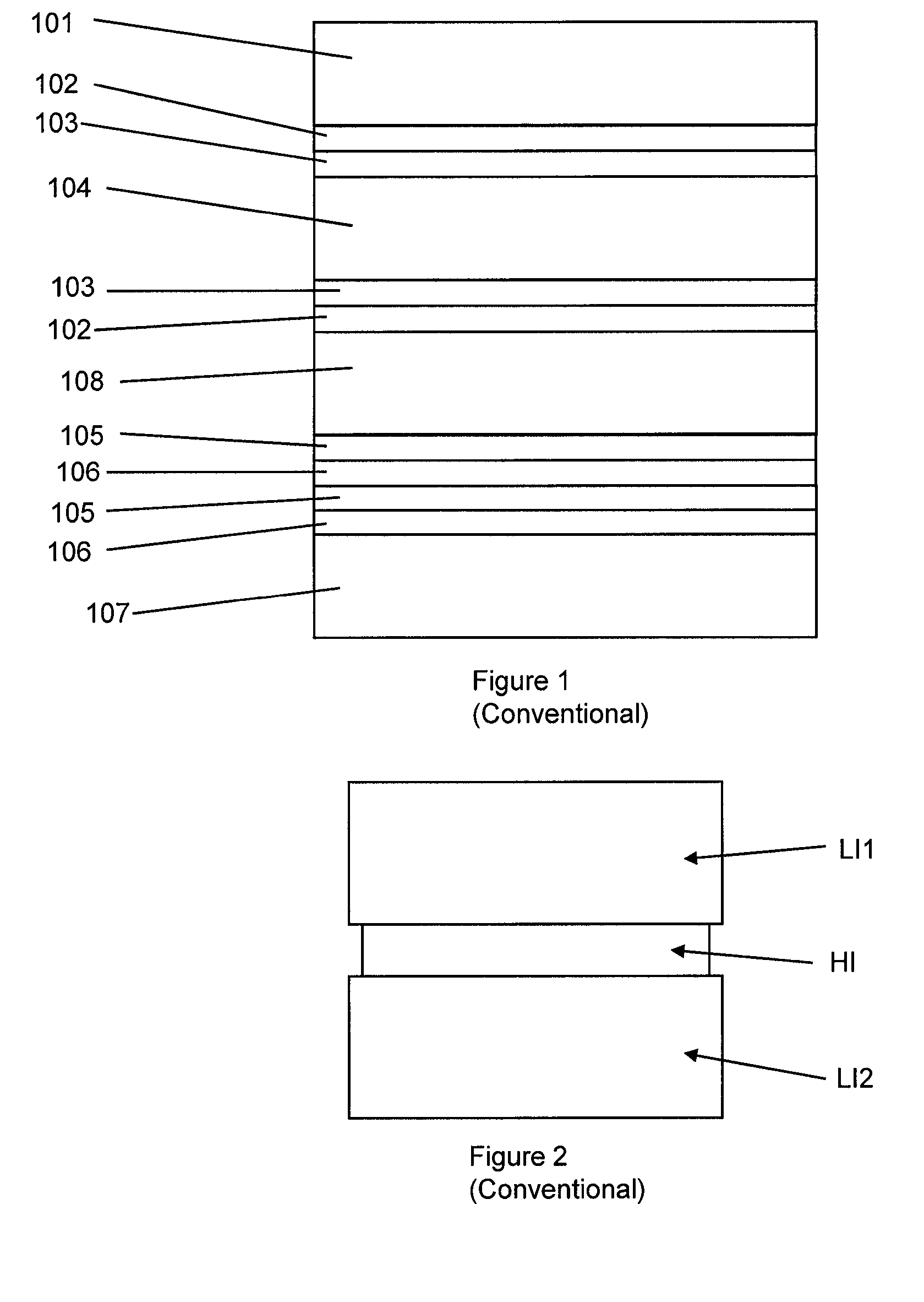
[0054]Referring to FIG. 1, there is shown an example of an optical structure embodied as a liquid crystal display (LCD), where one ITO electrode, 102, with n≈1.95, lies between layers of liquid crystal (LC), 104, with n≈1.53, and glass or color filter (CF), 101, with n≈1.53, and the other lies between LC, 104 and a planarizing resin, 108, with n≈1.59. There is also a thin layer of polyimide (PI), 103, with n≈1.70, between the LC and each ITO electrode. There are also layers of silicon nitride, 105, with n≈2.04, between layers of silica, 106, with n≈1.55 and / or the planarizing resin. The silica and silicon nitride layers are used as dielectric and for passivation in and around the TFT system. Glass, 107, supports the structure. This is one typical structure in use in the industry, and is also described in Table 1, with thickness also given for each layer.

[0055]

TABLE 1Label inRefractive indexMaterialFIG. 1(approximate)ThicknessColor filter (CF)1011.50>10 μmITO1021.95138 nmPolyimide (P...

embodiment 2

[0063]It is also possible to remove the silica and / or silicon nitride from the areas through which light is transmitted in an LCD. This is because they are only required around the TFT and circuitry in the device. Light is not transmitted through these regions (it is either reflected by metal or absorbed in the commonly used black mask), and so they can be considered irrelevant for purposes of reducing internal reflections. The silica and silicon nitride can in principle be patterned so that they are only found in these opaque regions, not in the transparent part of the pixel. In this case, the structure is as given in Table 4 and FIG. 7.

[0064]The structure described in Table 3 has the thicknesses of PI and ITO optimized to minimize total reflectivity by destructive interference. The total reflectivity of this structure is 0.015; 1.5% of incident light is reflected by this internal structure.

[0065]

TABLE 4Label inRefractive indexMaterialFIG. 7(approximate)ThicknessColor filter (CF)10...


PUM

PropertyMeasurementUnit
reflectivityaaaaaaaaaa
thickaaaaaaaaaa
thicknessesaaaaaaaaaa

Abstract

A structure for reducing internal reflections in an optical system includes a stack of layers including a first layer having a first refractive index, a second layer having a second refractive index, a third layer having a third refractive index, a fourth layer having a fourth refractive index, and a fifth layer having a fifth refractive index. The second layer is arranged between the first layer and the third layer, and the fourth layer is arranged between the third layer and fifth layer. Further, the third refractive index is greater than the second and fourth refractive indexes, the second refractive index is greater than the first refractive index, and the fourth refractive index is greater than the fifth refractive index.

Description

TECHNICAL FIELD[0001]The present invention relates generally to optical systems and, more particularly, to a display structure that uses destructive interference of light to cost-effectively reduce reflections at higher-refractive index layers within an optical system.BACKGROUND OF THE INVENTION[0002]Many optical systems contain layers of contrasting refractive index, n. This gives rise to reflections within the system, diverting incident light from its designed path, decreasing efficiency and increasing noise. More particularly, several systems contain a higher-refractive index medium surrounded by two lower-refractive index media. In some such systems the higher-index medium is thin enough so that interference between reflections at the two surfaces of the higher-index layer can take place, constructively or destructively, depending on the optical path difference.[0003]One such system illustrated in FIG. 1 is a liquid crystal display (LCD), where one indium-tin-oxide (ITO) electro...

Claims


Application Information

Patent Timeline
Patent Type & Authority Patents(United States)
IPC IPC(8): G02B1/11
CPCB32B7/02C09K19/02G02B1/111Y10T428/10Y10T428/24942Y10T428/1036C09K2323/03C09K2323/00
Inventor CURD, ALISTAIR P.
Owner UNIFIED INNOVATIVE TECH
Why Eureka
Try Eureka