Electrochemical potentiometric sensing without reference electrode

Active Publication Date: 2011-08-25
NXP BV
View PDF13 Cites 20 Cited by
  • Summary
  • Abstract
  • Description
  • Claims
  • Application Information

AI Technical Summary

Benefits of technology

[0048]In a third aspect, the invention relates to an RFID-tag comprising an electrochemical sensor in accordance with the invention. The invention is advantageously applied in this application area.
[0051]calculating the charged particle concentration from locations of the at least two measurement points of said curve.
[0052]The advantages and effects of the method in accordance with the invention follow that of corresponding embodiments of the electrochemical sensor. The inventors have realized that the particle concentration information is hidden in the slope of the surface-potential versus interface-temperature curve. A vertical shift of said curve does not have any influence on the slope. Thus any constant potential offset caused by an undefined DC potential of the analyte does not have an effect on the measured slope and consequently the determined charged particle concentration. As explained earlier for the sensor, two electrodes having a similar configuration can be used. There is no more a need for a reference electrode. Nevertheless, it is still possible to add a reference electrode in order to define the DC potential of the analyte. Such an embodiment is advantageous in case the DC-potential of the analyte tends to change during

Problems solved by technology

However, it is impossible to control or measure this surface

Method used


Image

  • Electrochemical potentiometric sensing without reference electrode
  • Electrochemical potentiometric sensing without reference electrode
  • Electrochemical potentiometric sensing without reference electrode

Examples


Embodiment Construction

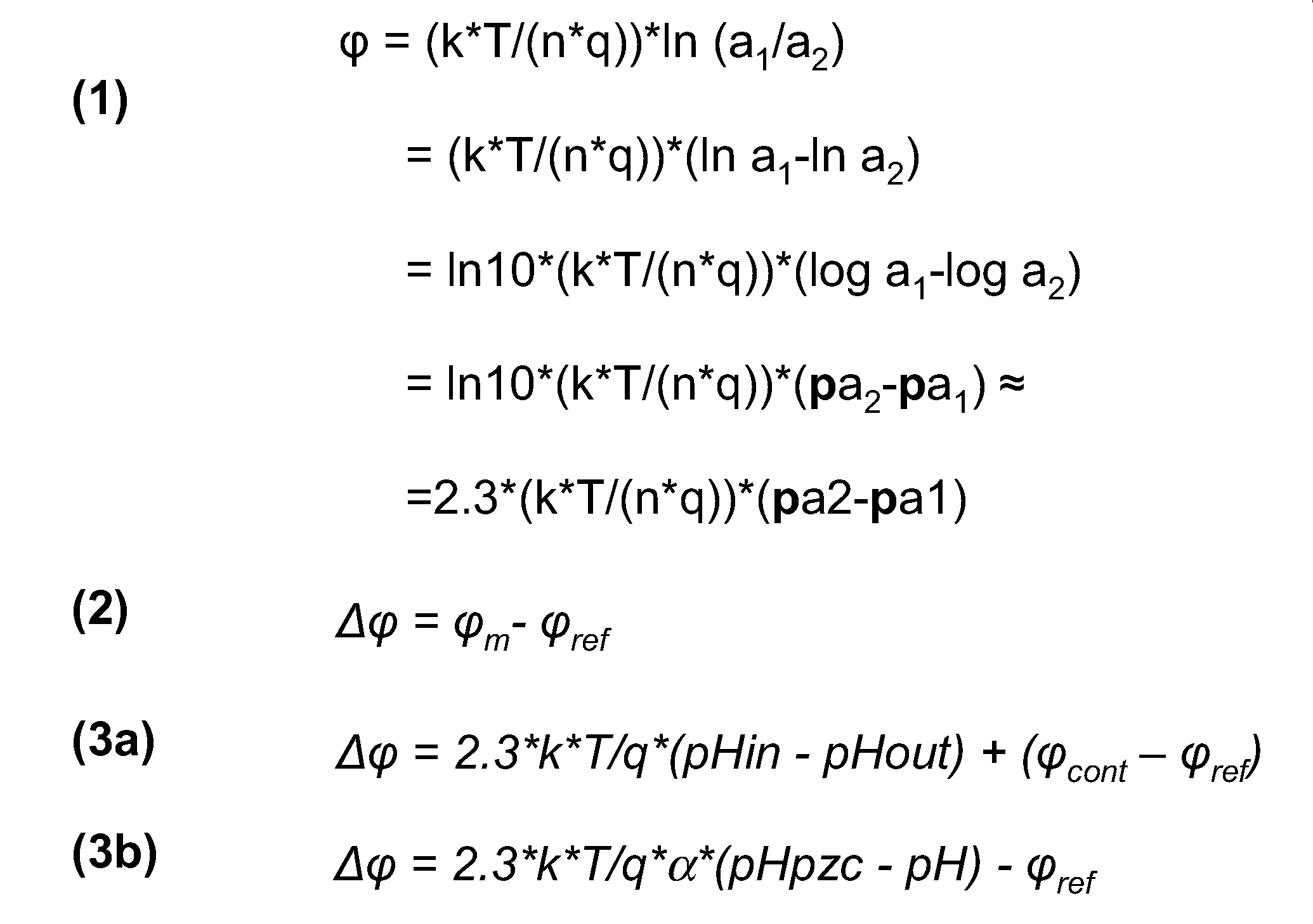
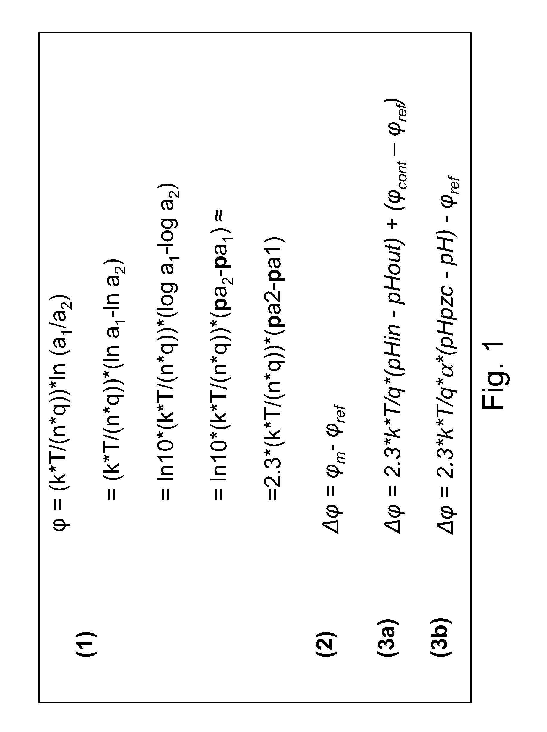
[0074]The invention provides a new method for determining a charged particle, i.e. ions and charged biomolecules, concentration in a liquid analyte. In an embodiment the method concerns determination of a hydrogen ion concentration and thereby the pH-value. It is based on surface-potential measurements at different temperature differences of two electrode analyte interfaces. The electrochemical sensor comprises a first electrode (with a first ion-sensitive sensor dielectric) and a second electrode (with a second ion-sensitive dielectric). The first electrode may be part of an ISFET, an EGFET, or an EIS capacitor. The second electrode may comprise the same layers and materials as the first electrode, which is one of the key advantages over the known electrochemical sensors. The charged particle concentration is calculated from the surface-potential versus temperature curve which is obtained by determining the potential difference between the first electrode and the second electrode a...


PUM


Abstract

The invention relates to a method of determining a charged particle concentration in an analyte (100), the method comprising steps of: i) determining at least two measurement points of a surface-potential versus interface-temperature curve (c1, c2, c3, c4), wherein the interface temperature is obtained from a temperature difference between a first interface between a first ion-sensitive dielectric (Fsd) and the analyte (100) and a second interface between a second ion-sensitive dielectric (Ssd) and the analyte (100), and wherein the surface-potential is obtained from a potential difference between a first electrode (Fe) and a second electrode (Se) onto which said first ion-sensitive dielectric (Fsd) and said second ion-sensitive dielectric (Ssd) are respectively provided, And ii) calculating the charged particle concentration from locations of the at least two measurement points of said curve (c1, c2, c3, c4). This method, which still is a potentiometric electrochemical measurement, exploits the temperature dependency of a surface-potential of an ion-sensitive dielectric in an analyte. The invention further provides an electrochemical sensor deny for determining a charged particle concentration in an analyte. The invention also provides various sensors which can be used to determine the charged particle concentration, i.e. EGFET's and EIS capacitors.

Description

FIELD OF THE INVENTION[0001]The invention relates to an electrochemical sensor for determining a charged particle concentration in an analyte, a semiconductor device comprising such sensor, an RFID tag comprising such sensor, and to a method of determining a charged particle concentration in an analyte.BACKGROUND OF THE INVENTION[0002]The pH-value is an integral parameter of every (aqueous) solution. It describes to which degree the solution is alkaline or acidic. Over a wide range it is well approximated by: pH=−log10 [H+], wherein [H+] denotes the hydrogen ion concentration of the solution in mol / L. Measuring a pH-value of an aqueous solution is a routine task in the industry and also in laboratories for process control and analysis. However, it could also become interesting for a wider range of applications if the pH-measurement units (sensor plus electronics) become sufficiently inexpensive. For example, there is a large potential for pH-measurement to monitor the quality of (li...

Claims


Application Information

Patent Timeline
IPC IPC(8): G06F19/00
CPCG01N27/4148G01N27/4145
Inventor MERZ, MATTHIASPONOMAREV, YOURI VICTOROVITCHCURATOLA, GILBERTO
Owner NXP BV
Why Eureka
Try Eureka