Disc mill assembly for a pulverizing apparatus

a pulverizing apparatus and disc mill technology, applied in the direction of chemistry apparatus and processes, grain treatment, agriculture, etc., can solve the problems of difficult manufacturing and maintenance of grinding disks with the aforementioned taper, difficult manufacturing of grinding disks, and high cost, so as to reduce shipping costs, reduce weight, and save costs.

Active Publication Date: 2011-09-01
REDUCTION ENG
View PDF6 Cites 9 Cited by
  • Summary
  • Abstract
  • Description
  • Claims
  • Application Information

AI Technical Summary

Benefits of technology

[0013]Another advantage of the present invention is that the grinding disks are lighter weight, resulting in even greater costs savings to the consumer due to reduced shipping costs, and also providing better contact between the water jacket and the grinding disk for cooling purposes. Additionally, the improved grinding disks have a greater cutting surface area that provides increased material throughput,
[0014]Yet another advantage of the present invention is that overall operating costs for a pulverizing system with the improved disc mill assembly are less than comparable previous systems, because grinding disks do not have to be sent away for re-sharpening, temporary replacement grinding disks do not have to be purchased and stored, and pulverizing systems of the present invention encounter less frequent down time due to worn grinding disks.
[0015]Yet another advantage of the present invention is that manufacturing grinding disks with planar, or flat, surfaces is more cost efficient than producing grinding disks with the traditional tapered cutting surface.
[0016]Still other benefits and advantages of the invention will become apparent to those skilled in the art to which it pertains upon a reading and understanding of the following detailed specification.

Problems solved by technology

Previously, disc mill assembly grinding disks were difficult to manufacture and maintain in operational condition.
Unfortunately, the manufacture of grinding disks having the aforementioned taper is difficult and expensive; it would be preferable to manufacture a grinding disk with a flat cutting surface having the same functionality of a tapered grinding disk.
Additionally, in order to withstand the forces exerted during the grinding operation, grinding disks have traditionally been heavy and thick metal devices.
Thus, grinding disks were traditionally returned to the manufacturer for re-sharpening after a relatively short period of use, and the costs associated with maintaining a pulverizing system included both re-sharpening charges and shipping fees for regularly transporting the heavy devices round trip for maintenance.

Method used


Image

  • Disc mill assembly for a pulverizing apparatus
  • Disc mill assembly for a pulverizing apparatus
  • Disc mill assembly for a pulverizing apparatus

Examples


Embodiment Construction

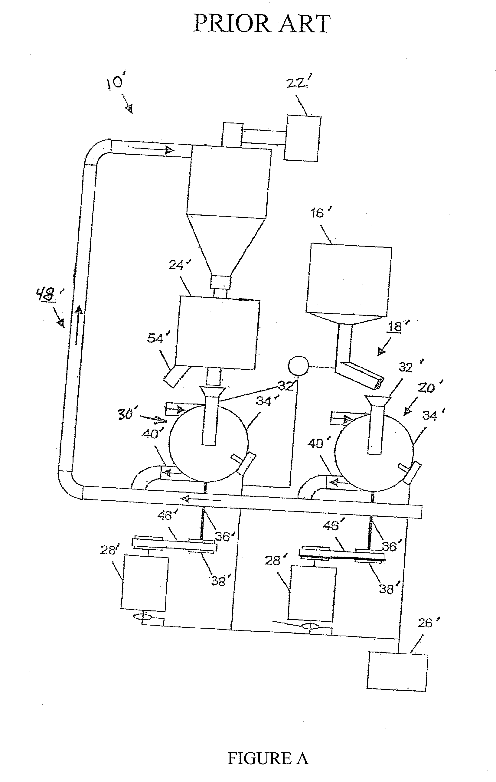
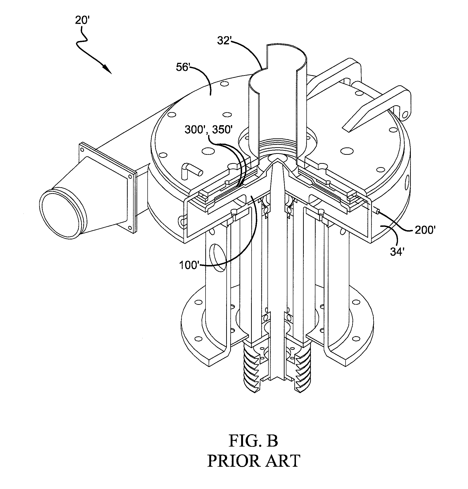
[0025]Referring now to the drawings, wherein the showings are for purposes of illustrating prior art pulverizing systems and embodiments of the present invention only and not for purposes of limiting the same, FIG. A shows a prior art schematic diagram of a pulverizing system 10. Most pulverizing systems 10 (hereafter, pulverizing apparatus) utilize the following component parts: primary and secondary disc mill assemblies 20′, 30′, a hopper bin 16′, means for moving materials from the hopper bin 16′ into the disc mill assembly 20′, 30′ (such means typically comprising a vibrating feeder 18′), a blower 22′, a sifter 24′, and a control panel 26′ for controlling the operation of motors 28′. Each of the disc mill assemblies 20′, 30′ preferably includes a material input channel 32′, a housing 34′, a spindle 36′, a pulley 38′, and a disc mill outlet 40′.

[0026]With continuing reference to FIG. A, the control panel 26′ is in communication with the vibrating feeder 18′, blower 22′, and motor...


PUM

PropertyMeasurementUnit
angleaaaaaaaaaa
angleaaaaaaaaaa
heightsaaaaaaaaaa

Abstract

This invention relates to the art of methods and apparatuses for grinding various materials into smaller particles; particularly, to those known in the art as pulverizing systems and devices. This invention provides methods and apparatuses for an improved disc mill assembly that utilizes a tapered flywheel and water jacket in conjunction with planar grinding disk cutting devices to create a tapered grinding channel.

Description

BACKGROUND OF THE INVENTION[0001]A. Field of Invention[0002]This invention pertains to the art of methods and apparatuses for grinding various materials into smaller particles; particularly, to those known in the art as pulverizing systems and devices.[0003]B. Description of the Related Art[0004]Pulverizing systems with one or more disc mill assemblies are well known in the art. Pulverizing systems are used to grind pelletized or shredded plastics, nylons, polyesters and other polymers into powder; although it is to be understood that the invention could also be useful in other industrial applications. Such systems have traditionally included a hopper bin for storing input polymer materials, means for feeding the input material to the disc mill assembly, means for carrying the processed ground material from the disc mill assembly to a sorting module, means for transporting acceptable ground material to a ground material collection area, and a means for recirculating unacceptable gro...

Claims


Application Information

Patent Timeline
Patent Type & Authority Applications(United States)
IPC IPC(8): B02C19/00B02C1/08
CPCB02C7/12B02C7/17Y10T29/49947Y10T29/49826B23P11/00
Inventor SLY, ROBERTGORHAM, ERICBAKER, LARRY
Owner REDUCTION ENG
Why Eureka
Try Eureka