Diagnosis management system and diagnosis management method for a valve-controlled hydrostatic displacement unit

a management system and hydrostatic displacement technology, applied in the direction of rotary clutches, instruments, fluid couplings, etc., can solve the problems of fpga itself being furthermore vulnerable to malfunction and difficult to analyze, and lacking diagnostic capabilities and evaluation logic units for errors in the control part,

Inactive Publication Date: 2011-09-08
ROBERT BOSCH GMBH
View PDF0 Cites 3 Cited by
  • Summary
  • Abstract
  • Description
  • Claims
  • Application Information

AI Technical Summary

Benefits of technology

[0011]One fundamental idea of the invention is to implement a diagnosis management system and a diagnosis administration or management as well as a plausibility check of system variables and sensor values, such as a temperature, a pressure, set-point and actual values for these, among others, and / or the direction of rotation, for a valve-controlled hydrostatic displacement unit or digital displacement unit or piston engine by reinforcing and furnishing diagnostic interfaces in hardware, in software, and in the form of models for sturdy operation under valid operating conditions. On the basis of well-founded outcomes of diagnosis, corrective intervention can then be done in the sequence control of the hydrostatic displacement unit, as a result of which the hydrostatic displacement unit is advantageously prevented from becoming unstable, and the sturdiness and intrinsic safety of the hydrostatic displacement unit and of the overall system can be improved.

Problems solved by technology

While the aforementioned type of drives has considerable advantages, particularly in the automotive field, or in other words for motor vehicles, in that case for instance as a gear-axle drive unit, such as a fast response speed and inherent energy efficiency from high efficiency, nevertheless it lacks diagnostic capabilities and evaluation logic units for errors in the control part, especially of the hydrostatic valve-controlled displacement unit or digital displacement unit, and more precisely for errors in the power electronics employed there.
Because of the lack of feedback between the components, sources of error can be located only with difficulty.
The FPGA itself is furthermore vulnerable to malfunction and difficult to analyze.
Finally, the use of FPGAs in the automotive field might not be permissible in every case.
Accordingly, the known triggering chain for a digital displacement unit, which is based on the use of an FPGA, has no diagnostic capabilities, so that errors cannot be detected, no information exchange between the components of the triggering chain can take place, and thus in the system no reactions to any errors in the system can take place.
Hence there is a problem, in that a higher-order control and / or regulating system in the event of error will receive no information about the type and severity of the error in the digital displacement unit.
The result can be damage in components, lines, and the like—those that carry pressure, for instance.
Until now, errors in the system could be detected only by experience with the system in operation, so that expensive system maintenance was furthermore disadvantageously absolutely necessary.

Method used


Image

  • Diagnosis management system and diagnosis management method for a valve-controlled hydrostatic displacement unit
  • Diagnosis management system and diagnosis management method for a valve-controlled hydrostatic displacement unit
  • Diagnosis management system and diagnosis management method for a valve-controlled hydrostatic displacement unit

Examples


Embodiment Construction

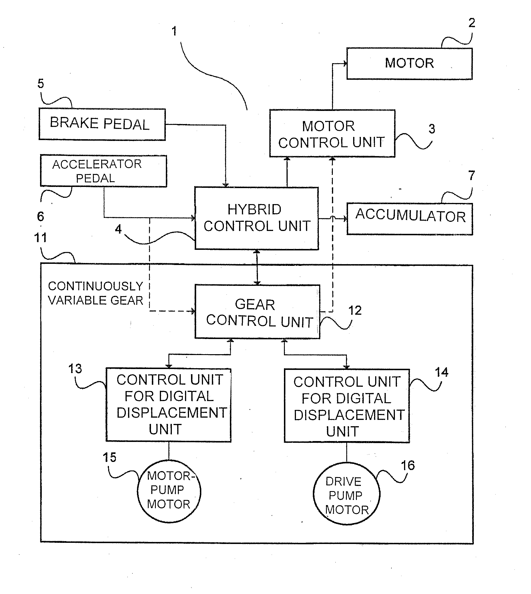
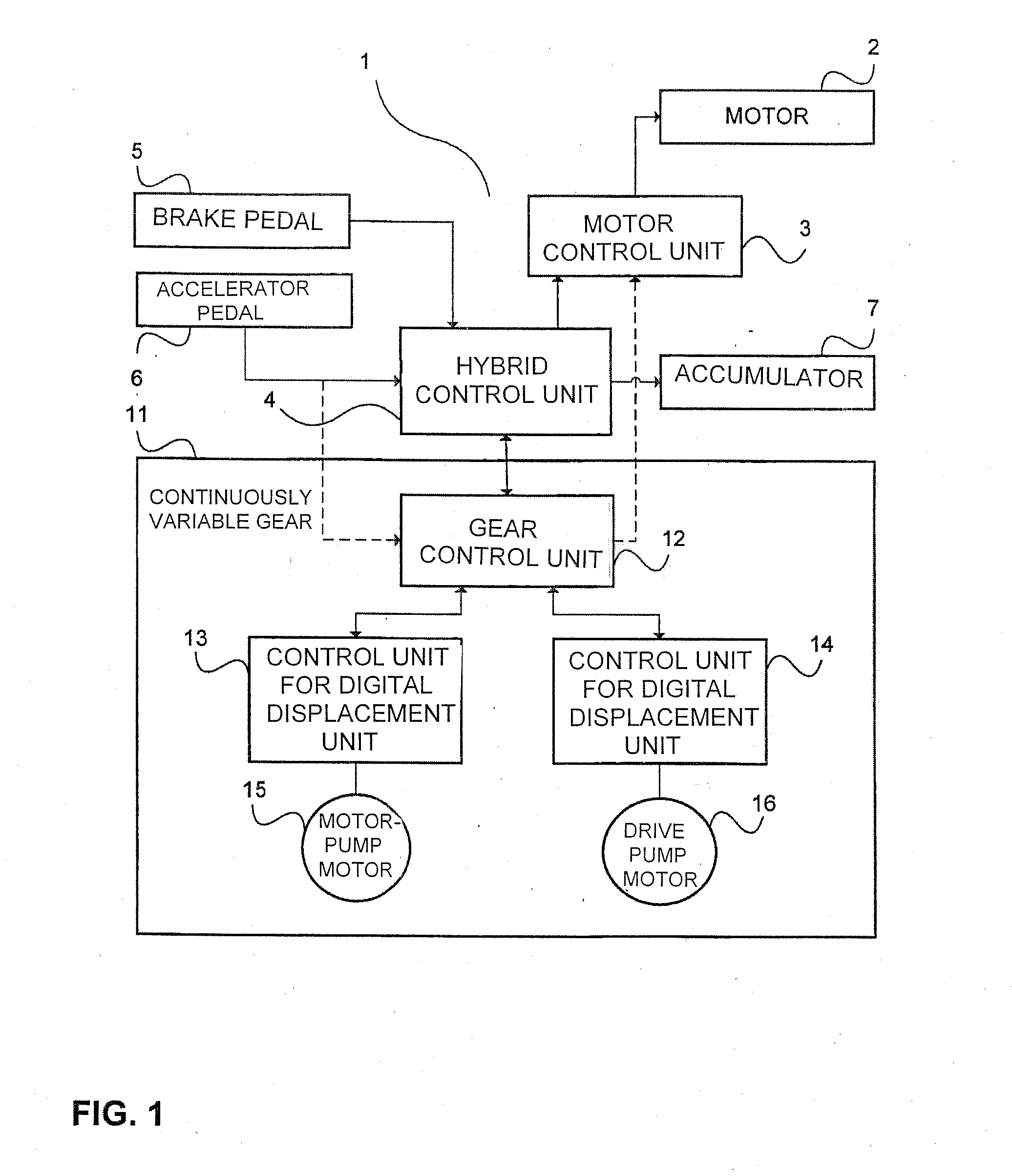
[0032]FIG. 1, in a block circuit diagram, in highly simplified form, shows a system overview of a valve-controlled hydrostatic displacement unit, as part of a drive system 1 of a vehicle. However, the invention is in no way limited to vehicles, but instead can be employed in any instance of use of hydrostatic displacement units. In the illustration in FIG. 1, the drive system 1 includes a motor 2, for instance in the form of a known internal combustion engine, which is controlled via a motor control unit, also known as an ECU, or engine control unit 3. The motor control unit receives control signals from a hybrid control unit (HCU) 4 and optionally (as indicated by a dashed arrow line) from a gear control unit 12, also called TCU or transmission control unit, which is part of a continuously variable gear 11, also known as an IVT, or infinitely variable transmission, or CVT, continuously variable transmission.

[0033]The hydrostatic displacement unit receives driver requests in the for...


PUM


Abstract

A diagnosis management system for a hydrostatic displacement unit, including a control unit for controlling a drive motor, a hybrid control unit for controlling the motor control unit on the basis of at least one desired acceleration signal and one desired deceleration signal for the drive motor, a gear control unit for controlling the motor control unit on the basis of at least signals derived from a continuously variable gear, and a control unit for a digital displacement unit, for controlling at least one pump motor as the digital displacement unit is disclosed. The control unit for a digital displacement unit has at least one diagnostic interface, which detects operating values and / or operating states in order to detect system errors in the pump motor, a sensor unit portion associated with the pump motor, and / or a power electronics portion associated with the pump motor; and at least one calculation portion, which preprocesses the operating values and / or operating states detected by the diagnostic interface. The at least one diagnostic interface and the at least one calculation portion are disposed for operating in a first system direction for diagnosis and for determining a correction of incident system errors, and in a second system direction for diagnosis and / or for performing the correction of incident system errors. A diagnosis management method can be performed by the diagnosis management system.

Description

CROSS-REFERENCE TO RELATED APPLICATION[0001]This application is based on German Patent Application 10 2009 058 736.9 filed on Dec. 15, 2009.BACKGROUND OF THE INVENTION[0002]1. Field of the Invention[0003]The invention relates to a diagnosis management system for a valve-controlled hydrostatic displacement unit and to a diagnosis management method performed with such a diagnosis management system.[0004]2. Description of the Prior Art[0005]Hydrostatic drives, comprising a hydropump which drives a hydromotor via a fluid line, have in the meantime gained wide use in mechanical and systems engineering but also in the automotive field. Among the hydraulic or hydrostatic displacement machines or hydromachines used in this field as drives are pumps and motors, which operate on the displacement principle and as a rule have the same structural layout. By suitable control of the fluid flow, pumps in particular can function as motors, and vice versa. Because of the distinction in the direction ...

Claims


Application Information

Patent Timeline
Patent Type & Authority Applications(United States)
IPC IPC(8): F15B13/02B60W50/02
CPCB60W10/06B60W50/0205B60W10/103B60W10/08B60W2050/0006
Inventor LOPEZ PAMPLONA, ALEJANDROBEUTER, BJOERN
Owner ROBERT BOSCH GMBH
Why Eureka
Try Eureka