Controller for engine cooling system

a technology for controlling a cooling system and an engine, which is applied in the direction of machines/engines, indirect heat exchangers, lighting and heating apparatus, etc., can solve the problems of frequent stop and restart of equipped engines, deterioration of fuel consumption efficiency, and above problems, so as to achieve sufficient heating and increase the air temperature through the second exchanging portion

Inactive Publication Date: 2011-09-08
DENSO CORP
View PDF14 Cites 59 Cited by
  • Summary
  • Abstract
  • Description
  • Claims
  • Application Information

AI Technical Summary

Benefits of technology

[0011]The present invention is made in view of the above matters, and it is an object of the present invention to provide a controller for an engine cooling system, which is capable of improving an anti-knocking ability even when the engine is restarted. Further, it is another object of the present invention to provide an air-conditioner for an automobile which can sufficiently heat a passenger compartment by use of an engine coolant passed through a cylinder head.

Problems solved by technology

If the engine is restarted with the cylinder head of high temperature, fuel consumption efficiency may be deteriorated.
Especially, in a vehicle having an idle reduction function and a vehicle having a hybrid engine, the equipped engine is frequently stopped and restarted.
Thus, the above problems often occur.
When the engine coolant passed through only the cylinder head is used as a heat source for heating a passenger compartment, it is likely that the air temperature can not be increased enough.

Method used


Image

  • Controller for engine cooling system
  • Controller for engine cooling system
  • Controller for engine cooling system

Examples


first embodiment

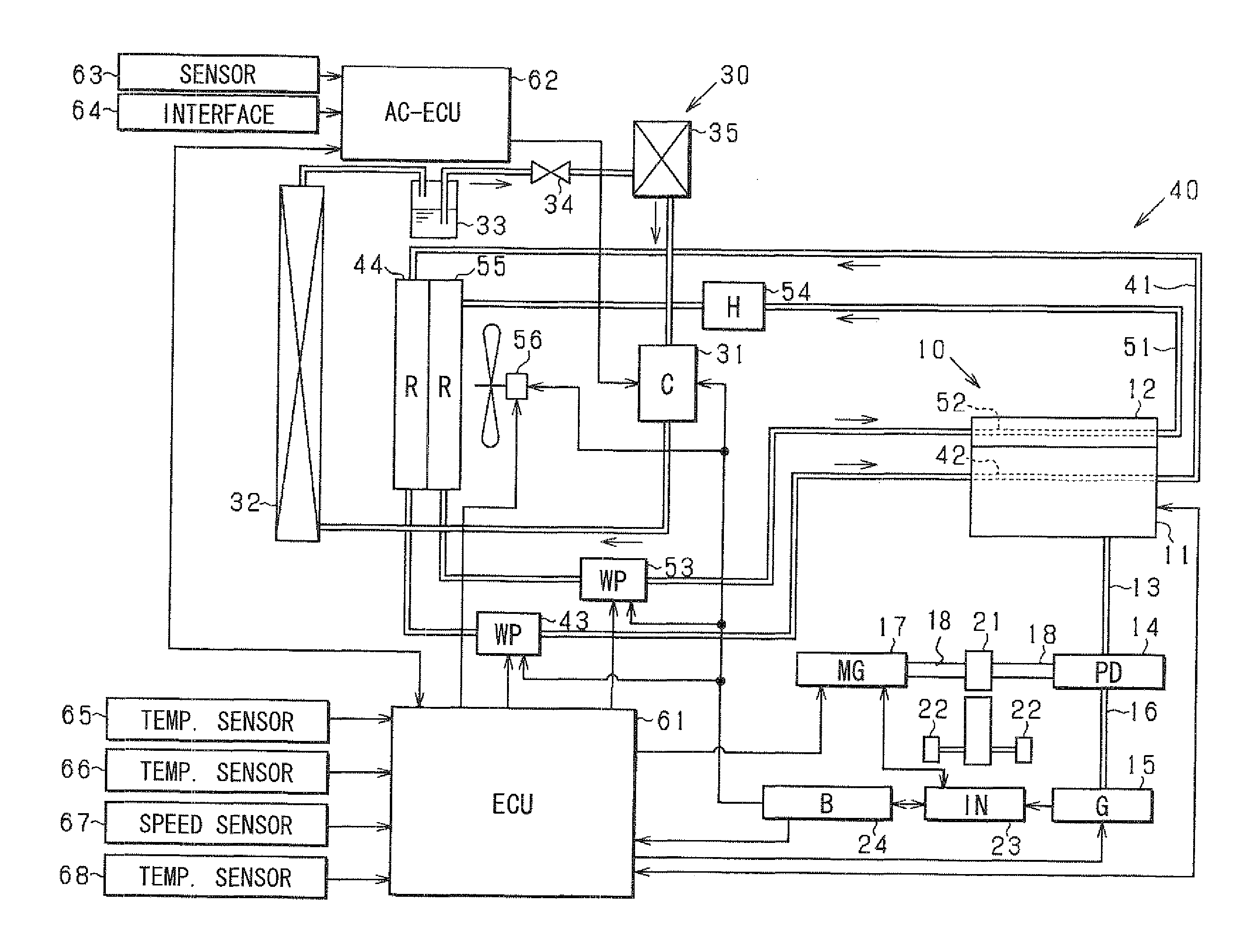
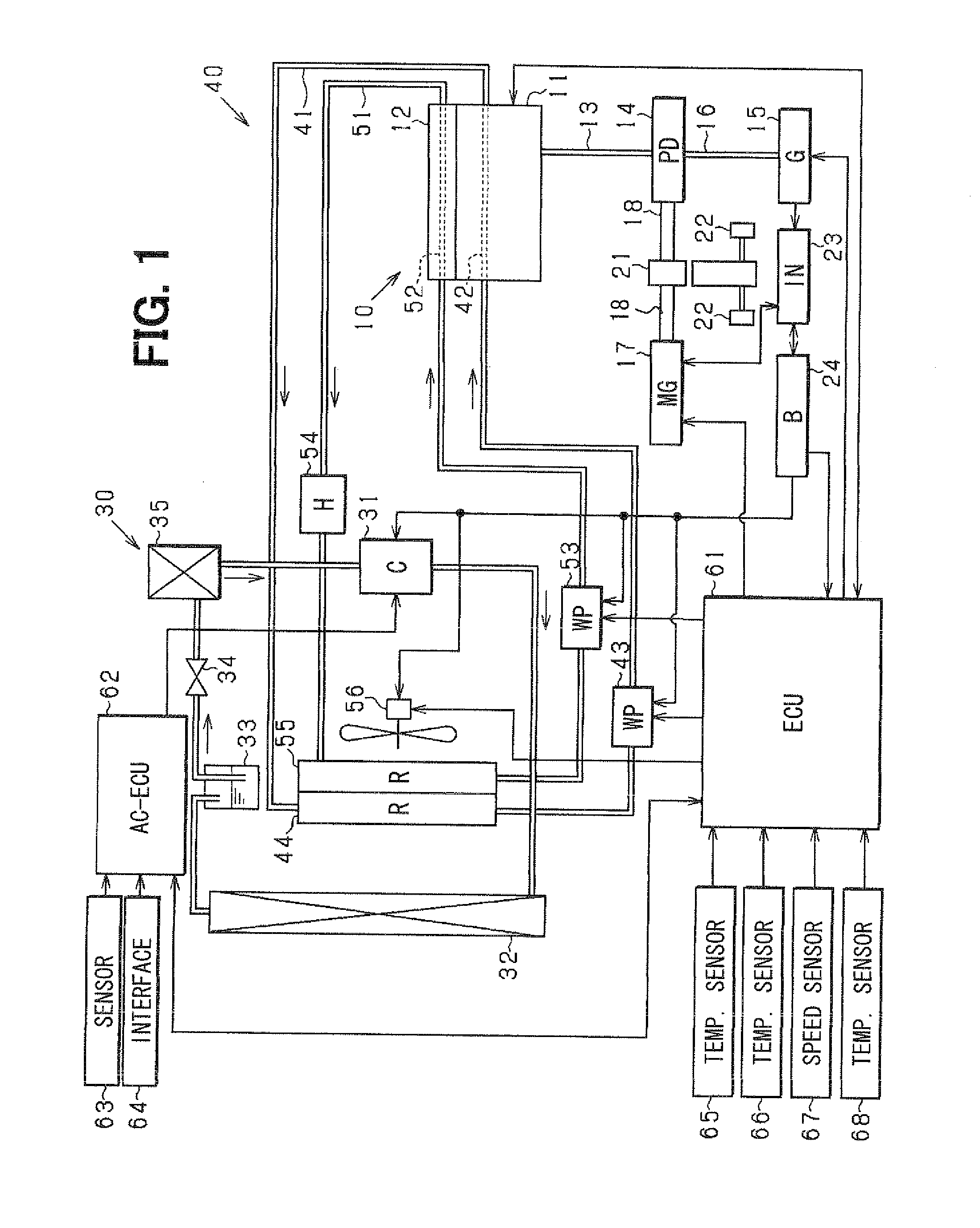
[0044]Hereinafter, a first embodiment that embodies the present invention will be described with reference to the drawings. In the present embodiment, a vehicle is equipped with a hybrid engine. FIG. 1 schematically shows an entire configuration of a control system in a first embodiment.

[0045]A vehicle is equipped with an internal combustion engine 10. The engine 10 is comprised of a cylinder block 11 and a cylinder head 12. The cylinder block 11 has a cylinder (not shown) in which a piston is slidably provided. The cylinder head 12 is provided on the cylinder block 11 to define a combustion chamber.

[0046]When air-fuel mixture is combusted in the combustion chamber, the piston slides downward. An output shaft 13 of the engine 10 is connected to a power distribution portion 14. The power distribution portion 14 has a planetary gear mechanism including a planetary gear, a sun gear and a ring gear. The planetary gear is connected to the output shaft 13 of the engine 10, the sun gear is...

second embodiment

[0113]As shown in FIG. 8A, the cylinder-block-passage and the cylinder-head-passage can be combined as one passage.

[0114]Specifically, a flow rate control valve 73 is disposed at a branch portion of the water jackets 42, 52. According to control signals from the ECU 61, the flow rate control valve 73 controls the flow rate of engine coolant flowing through each water jacket 42, 52. A water temperature sensor is provided to each of outlets of the water jackets 42, 52 to detect the head-coolant temperature “Thead” and the block-coolant temperature “Tblock”. The ECU 61 controls the water pump 72 and the flow rate control valve 73 in order to control the head-coolant temperature “Thead” and the block-coolant temperature “Tblock”.

[0115]A thermostat 74 is provided in the coolant passage. A bypass passage 75 is provided which bypasses the radiator 71. When the engine coolant temperature is low, the engine coolant flows through the bypass passage 75. The thermostat 74 is a well known mechan...

third embodiment

[0125]FIG. 9 schematically shows an entire structure of an air conditioner according to third embodiment. An air-conditioner is provided to a hybrid vehicle.

[0126]The air-conditioner 101 is provided with a first coolant circuit 110 and a second coolant circuit 120. The engine coolant passed through a cylinder head 131 flows in the first coolant circuit 110. The first coolant circuit 110 includes a first heater core 111, a first water pump 112, and a first temperature sensor 113. The engine coolant passed through a cylinder block 132 flows in the second coolant circuit 120. The second coolant circuit 120 includes a second heater core 121, a second water pump 122, and a second temperature sensor 123.

[0127]A cylinder block 132 and a cylinder head 131 of the engine 130 have well-known configuration.

[0128]The cylinder head 131 has a first coolant inlet 131a and a first coolant outlet 131b. The engine coolant flows through a coolant passage formed in the cylinder head 131. The coolant flo...


PUM


Abstract

An internal combustion engine has a cylinder-head-passage through which an engine coolant flows toward a water jacket when a water pump is operated. The water pump is an electric water pump utilizing the electric power charged in the battery. A radiator is provided in the cylinder-head-passage. Even after the engine is shut off, the water pump is kept driven.

Description

CROSS-REFERENCE TO RELATED APPLICATION[0001]This application is based on Japanese Patent Applications No. 2010-46588 filed on Mar. 3, 2010, and No. 2010-49177 filed on Mar. 5, 2010, the disclosures of which are incorporated herein by reference.FIELD OF THE INVENTION[0002]The present invention relates to a controller for an engine cooling system. Further, the present invention relates to an air-conditioner for an automobile in which heating is performed by use of engine coolant.BACKGROUND OF THE INVENTION[0003]JP-8-144758A shows an engine cooling system in which engine coolant is circulated in order to cool a cylinder head and cylinder block of an engine. A mechanical water pump circulating the engine coolant is driven by a driving force transmitted from a crankshaft of the engine. While the engine is running, the mechanical water pump is also driven in order to circulate the engine coolant. A combustion chamber of the engine is also cooled, so that anti-knocking ability is improved....

Claims


Application Information

Patent Timeline
Patent Type & Authority Applications(United States)
IPC IPC(8): F01P7/14F28D7/00
CPCF01P7/04F01P7/164F01P2003/027F01P2003/185F01P2005/105F01P7/02F01P2025/66F01P2031/30F01P2037/02F01P2060/08F01P2025/30F01P5/00F01P7/165
Inventor NISHIKAWA, MICHIOKAKEHASHI, NOBUHARUOTA, KOJI
Owner DENSO CORP
Why Eureka
Try Eureka