Power converter

a power converter and converter technology, applied in the direction of motor/generator/converter stopper, electronic commutator, dynamo-electric converter control, etc., can solve the difference in heat loss between the switching elements at the higher potential and the switching elements at the lower potential, and the inability to control the inverter current. the effect of ripple current reduction and suppression of heat loss differences

Active Publication Date: 2011-09-15
DENSO CORP
View PDF7 Cites 28 Cited by
  • Summary
  • Abstract
  • Description
  • Claims
  • Application Information

AI Technical Summary

Benefits of technology

[0008]It is an object of the invention to provide a power converter, which is capable of decreasing ripple current of a capacitor while suppressing a difference in heat loss between switching elements.

Problems solved by technology

In addition, fluctuation of a voltage applied to the inverter may result in poor controllability of inverter current.
However, the technique disclosed in JP 2001-197779A requires a delay circuit since the phase difference is imposed on the switching timings based on a modulation ratio and a power factor.
In addition, this technique requires detection of current in a plurality of lines at short intervals, which may result in heavy operation load of a control circuit.
If an integrated value of current flowing through the switching elements at the higher potential is significantly different from an integrated value of current flowing through the switching elements at the lower potential, it may result in a difference in heat loss between the switching elements at the higher potential and the switching elements at the lower potential.
In addition, this difference in heat loss may require additional elements in the switching elements at the higher potential and the switching elements at the lower potential, which may result in cost-up.

Method used


Image

  • Power converter
  • Power converter
  • Power converter

Examples


first embodiment

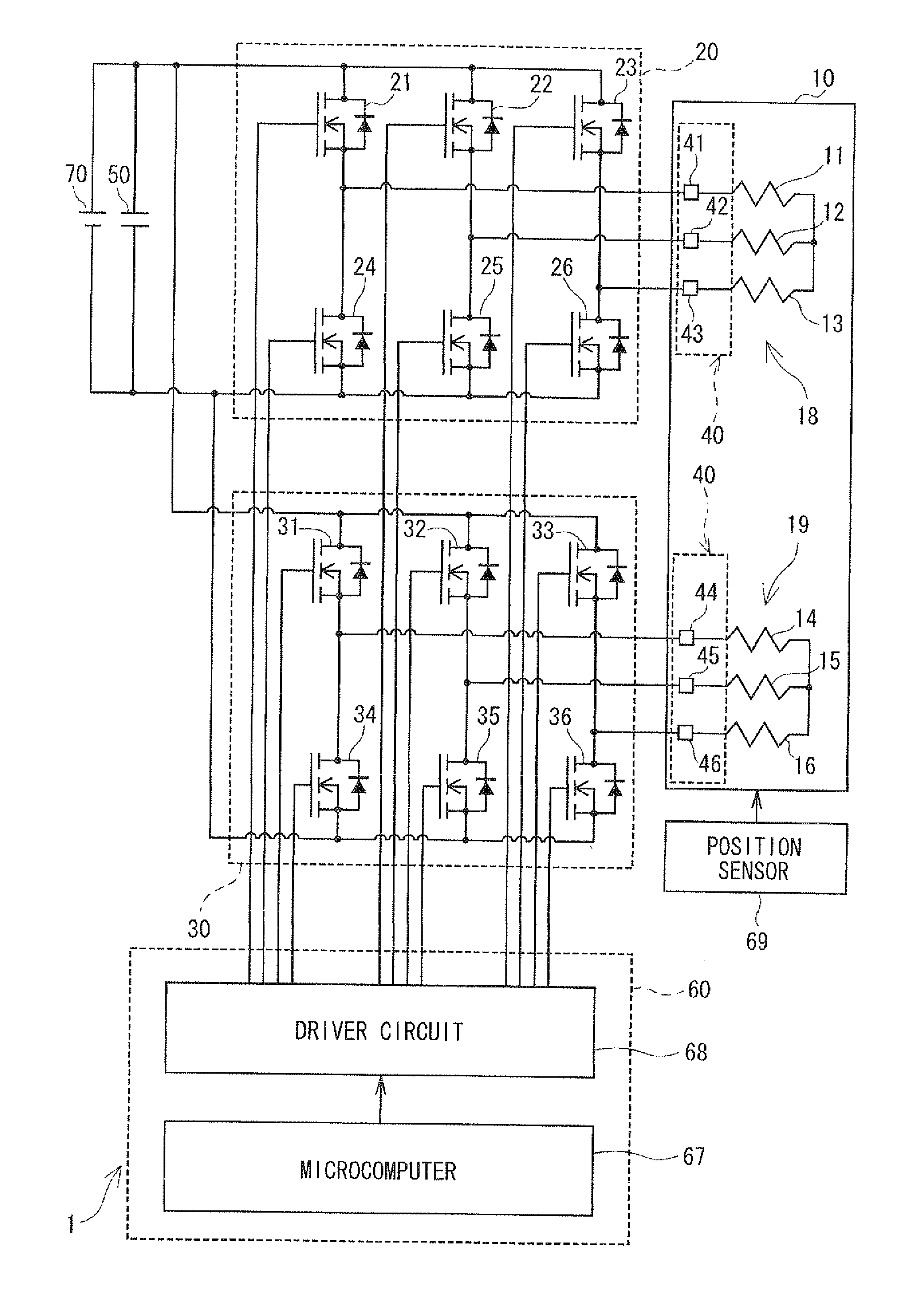
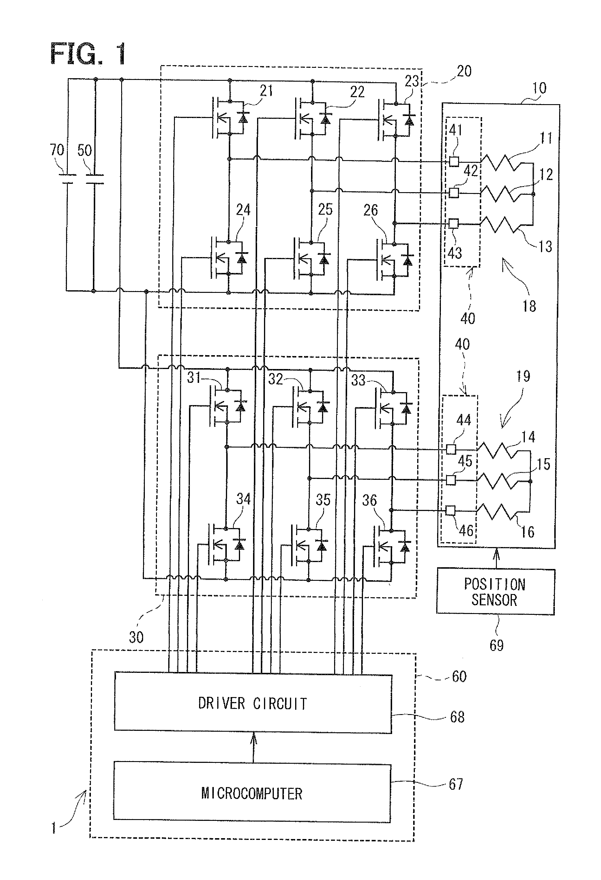
[0040]As shown in FIG. 1, a power converter 1 is provided to drive and control a motor 10, which is a multiphase rotating electric machine. For example, the power converter 1 is applied to an electric power steering system (EPS) for assisting in steering operation of a vehicle together with the motor 10.

[0041]The motor 10 is a three-phase brushless motor and has a rotor and a stator (both not shown). The rotor, which is a disc-like member, has a surface to which permanent magnets are attached, and has magnetic poles. The stator accommodates and rotatably supports the rotor. The stator has projections projecting inwardly in a radial direction at predetermined angle intervals, with the projections wound with a U1 coil 11, a V1 coil 12, a W1 coil 13, a U2 coil 14, a V2 coil 15 and a W2 coil 16. The U1 coil 11, the V1 coil 12 and the W1 coil 13 constitute a first set of windings 18. The U2 coil 14, the V2 coil 15 and the W2 coil 16 constitute a second set of windings 19. The first set o...

second embodiment

[0115]A second embodiment of the present invention is shown in FIGS. 13, 14A, 14B and 15A to 15C.

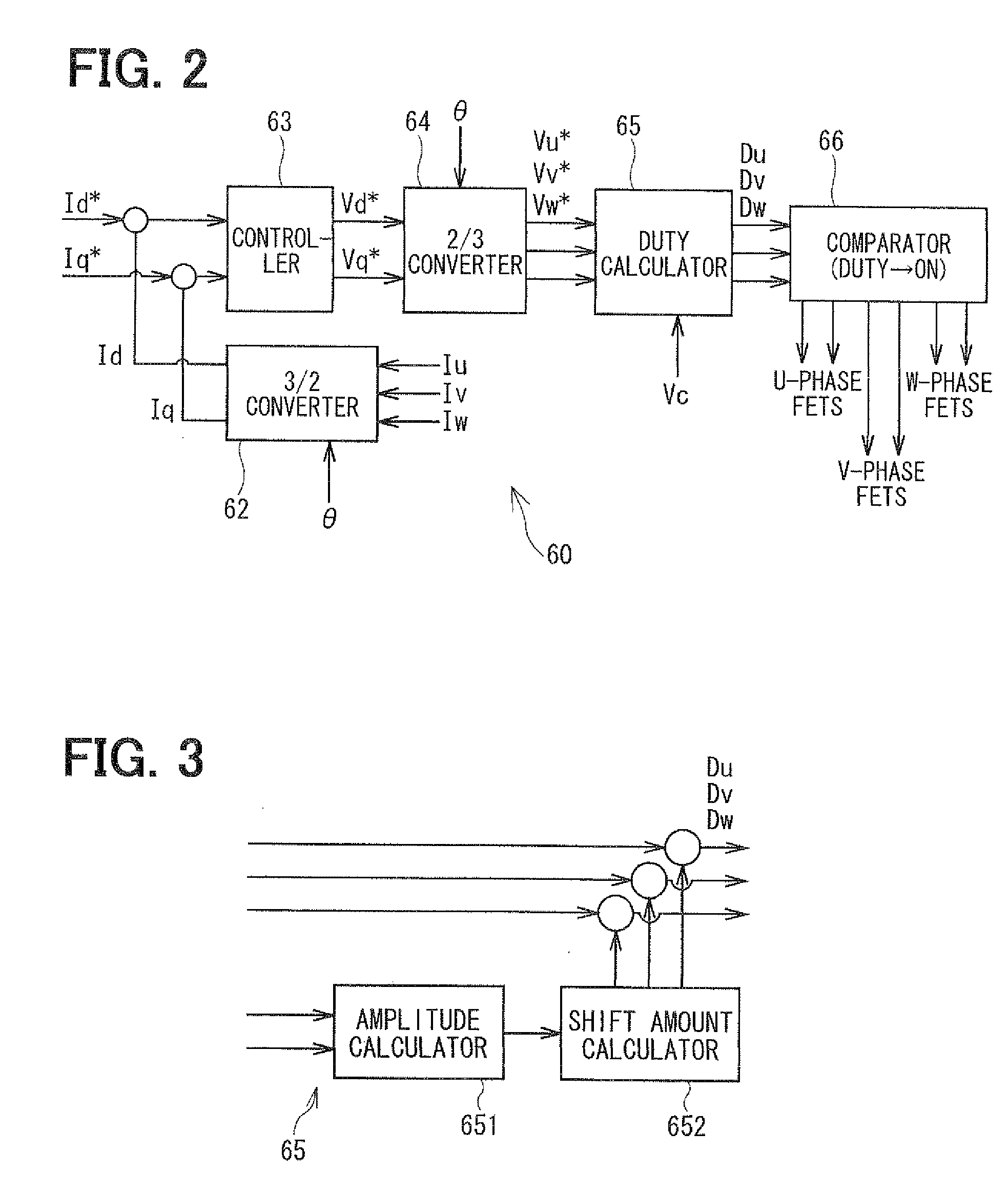
[0116]As shown in FIG. 13, the duty calculator 65 includes a modulator 653 in addition to the amplitude calculator 651 and the shift amount calculator 652. The modulator 653 performs a modulation process to modulate a waveform of a reference sinusoidal wave. The modulator 653 corresponds to a modulation part.

[0117]In the second embodiment, an over-duty correction process shown in FIGS. 14A and 14B is performed as the modulation process in the modulator 653. In the over-duty correction process, for a reference sinusoidal wave shown in FIG. 14A, subtraction is made from all phases by an amount exceeding the reference maximum value Smax and the reference minimum value Smin. This results in a waveform shown in FIG. 14B after over-duty correction. In addition, in the second embodiment, the amplitude of the reference sinusoidal wave before the correction is 1.154 (=2 / √3) times as large as an a...

third embodiment

[0127]A third embodiment of the present invention is shown in FIGS. 16A, 16B and 17A to 17C.

[0128]In the third embodiment, like the second embodiment, the duty calculator 65 includes the modulator 653, which performs a modulation process to modulate a waveform of a reference sinusoidal wave.

[0129]In the third embodiment, a maximum-minimum (max-min) duty equalization process shown in FIGS. 16A and 16B is performed as the modulation process in the modulator 653. In this process, a U-phase duty Du, a V-phase duty Dv and a W-phase duty Dw are calculated based on the following equations. In the following equations, Du′, Dv′ and Dw′ are U-phase, V-phase and W-phase duties before modulation, respectively. Dmax and Dmin are the maximum value and the minimum value of duty of each phase before modulation, respectively.

Du=Du′−(Dmax−Dmin) / 2  (1)

Dv=DV′−(Dmax−Dmin) / 2  (2)

Dw=Dw′−(Dmax−Dmin) / 2  (3)

[0130]Waveforms of duty command signals after correction, which are calculated based on the above equa...


PUM


Abstract

In a power converter, a voltage command signal shifting part shifts a first duty command signal such that a first duty center value related to a voltage applied to a first set of windings is shifted downwards than an output center value of a possible duty range. The voltage command signal shifting part also shifts a second duty command signal such that a second duty center value related to a voltage applied to a second set of windings is shifted upwards than the output center value. First and second shift amounts of the first and second duty center values from the output center value are varied depending on amplitude. Accordingly, ripple current of a capacitor can be decreased, and a difference in heat loss between switching elements can be minimized.

Description

CROSS REFERENCE TO RELATED APPLICATION[0001]This application is based on and incorporates herein by reference Japanese patent application No. 2010-53149 filed on Mar. 10, 2010.FIELD OF THE INVENTION[0002]The present invention relates to a power converter for a multiphase rotating electric machine.BACKGROUND OF THE INVENTION[0003]Techniques for controlling current to drive a multiphase rotating electric machine by part of pulse width modulation (PWM) have been known in the related art. For example, if the multiphase rotating electric machine is a three-phase motor, a PWM reference signal of a triangular wave or the like is compared with a voltage reference signal related to voltages applied respectively to its three-phase windings and current flowing through the three-phase motor is controlled by switching on and off switching elements of an inverter.[0004]If the inverter is connected to a capacitor, when no current flow into the inverter, the capacitor is charged as current flows fr...

Claims


Application Information

Patent Timeline
Patent Type & Authority Applications(United States)
IPC IPC(8): H02P23/00H02M7/48H02P6/06H02P6/08H02P6/12H02P6/28
CPCB62D5/046H02M1/15H02P27/08H02M2001/008H02P6/16H02M7/53875H02M1/008
Inventor SUZUKI, TAKASHI
Owner DENSO CORP
Why Eureka
Try Eureka