
Method for impulse noise mitigation

Active Publication Date: 2011-09-22
AIROHA TECH (SUZHOU) LTD
View PDF2 Cites 11 Cited by
  • Summary
  • Abstract
  • Description
  • Claims
  • Application Information

AI Technical Summary

Benefits of technology

[0012]Additional features and advantages of the present invention will be set forth in part in the description which follows, and in part will be obvious from the description, or may be learned by practice of the invention. The features and advantages of the invention will be realized and attained by means of the elements and combinations particularly pointed out in the appended claims.

Problems solved by technology

Due to channel dispersion or multi-path effect, interference or noise may corrupt the information signal on each tone as the signal travels through the communication channel (i.e., twisted pair telephone line) to the receiver.
In addition to additive white Gaussian noise (AWGN), near-end crosstalk (NEXT) and far-end crosstalk (FEXT), interference from alternating-current (AC) power lines is a significant source of impulsive noise on twisted pair phone lines.
The interference from impulse noise sources tends to be periodically impulsive, that is, relatively large in power level and short in duration.
In the presence of such repetitive impulsive or burst noise sources, if their effects are not properly mitigated, system parameters may deviate from their nominal or optimum values.
If the repetition rate of such impulsive noise is greater than the convergence rate of these system parameters' adaptation or estimation, deviations of the system parameters may accumulate and thus system performance may severely degrade.
Such an assumption may not be true in real applications, especially in the presence of strong impulse noise or interference.
The interference or impulse noise may severely degrade the quality of DSP and / or channel estimation for the setting of system parameters during the link setup stage, or significantly affect the adaptation or adjustment of system parameters in the showtime stage of data reception and transmission.

Method used


Image

  • Method for impulse noise mitigation
  • Method for impulse noise mitigation
  • Method for impulse noise mitigation

Examples


Embodiment Construction

[0023]Reference will now be made in detail to the present examples of the invention, examples of which are illustrated in the accompanying drawings. Wherever possible, the same reference numbers will be used throughout the drawings to refer to the same or like parts.

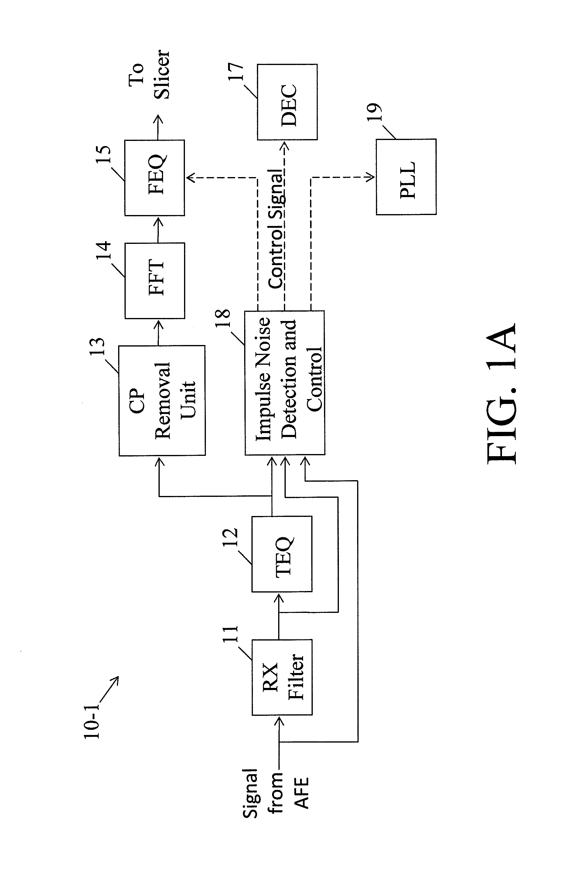
[0024]FIG. 1A is a block diagram of an apparatus 10-1 for impulse noise mitigation in the time domain in a multi-carrier communication system in accordance with an example of the present invention. Referring to FIG. 1A, the apparatus 10-1 may include a digital receiver filter 11, a time-domain equalizer (TEQ) 12, a cyclic prefix (CP) removal unit 13, a fast Fourier transform (FFT) module 14, a frequency-domain equalizer (FEQ) 15 and a controller 18 capable of impulse noise detection. The controller 18 may be configured to detect impulse noise in the time domain and, when impulse noise is detected, disable the adaption or update of system parameters so that the impact of impulse noise on the system parameters may be allev...


PUM


Abstract

A method of noise mitigation in a multi-carrier communication system includes receiving a signal from a decision device, determining whether synchronization symbol update is enabled, updating at least one of frequency-domain equalizer (FEQ) coefficients or digital echo canceller (DEC) coefficients in synchronization symbol periods if the synchronization symbol update is enabled, determining whether data symbol update is performed if the synchronization symbol update is not enabled, determining whether a flag associated with the signal is set if the data symbol update is not performed, and updating at least one of FEQ or DEC coefficients associated with the signal in synchronization symbol periods if the flag is set.

Description

BACKGROUND OF THE INVENTION[0001]The present invention relates generally to multi-carrier communication and, more particularly, to a method for mitigating impulse noise and interference in a multi-carrier communication system.[0002]Market demand for high data rates plays an important role in advanced communications. With the development of “digital signal processor” (DSP) and “very large scale integrated circuit” (VLSI) technology, the demand for video / audio services, consumer services, Internet, and Word Wide Web (WWW) grows exponentially. An advanced communication technology is needed to satisfy the requirement. Moreover, it may be important to take advantage of existing communication infrastructure to transfer data so that servers and clients can save the cost for building a new network. “Asymmetric digital subscriber line” (ADSL) has become a popular application because ADSL technology satisfies the demand for more throughput based on a currently available infrastructure. For ex...

Claims


Application Information

Patent Timeline
IPC IPC(8): H03H7/40
CPCH04B3/235H04J11/0066H04L25/03019H04L27/2675H04L27/2657H04L2025/03414H04L2025/03535H04L25/03159
Inventor YANG, SHU-FACHEN, MIN-CHIEHTZOU, CHING-KAE
Owner AIROHA TECH (SUZHOU) LTD
Features
  • Generate Ideas
  • Intellectual Property
  • Life Sciences
  • Materials
  • Tech Scout
  • Unparalleled Data Quality
  • Higher Quality Content
  • 60% Fewer Hallucinations
Learn More