Subject information processing apparatus, subject information processing method, and subject information processing program

a technology of subject information and processing apparatus, applied in the field of subject information processing apparatus, subject information processing method and subject information processing program, can solve the problems of noise elimination of part of the signal components, different waveform of the electric signal which was converted and output by the probe, and finite frequency bands of the probe, so as to improve the accuracy of noise elimination based on wavelet transform.

Inactive Publication Date: 2011-09-22
CANON KK
View PDF7 Cites 33 Cited by
  • Summary
  • Abstract
  • Description
  • Claims
  • Application Information

AI Technical Summary

Benefits of technology

[0011]With the foregoing in view, it is an object of the present invention to provide a technology to improve the accuracy of noise elimination based on a wavelet transform.
[0027]According to the present invention, the accuracy of noise elimination based on a wavelet transform can be improved.

Problems solved by technology

Actually however, the frequency bands of a probe are finite, so the waveform of the electric signal which was converted and output by the probe is different from an ideal waveform.
If the wavelet transform, of which mother wavelet is based on the signal waveform under ideal conditions, is performed on this signal waveform, a part of the signal components may be lost by noise elimination because the signal components and noise components cannot be seperated well.
As a result, a pathologically changed area may not be detected in the diagnostic image, or an artifact may be generated.
If the noise elimination intensity is weakened to prevent the generation of such a side effect, weak signals generated from a pathologically changed area deep in the measuring object may be obscured by the noise, which makes the area invisible in the diagnostic image.

Method used


Image

  • Subject information processing apparatus, subject information processing method, and subject information processing program
  • Subject information processing apparatus, subject information processing method, and subject information processing program
  • Subject information processing apparatus, subject information processing method, and subject information processing program

Examples


example 1

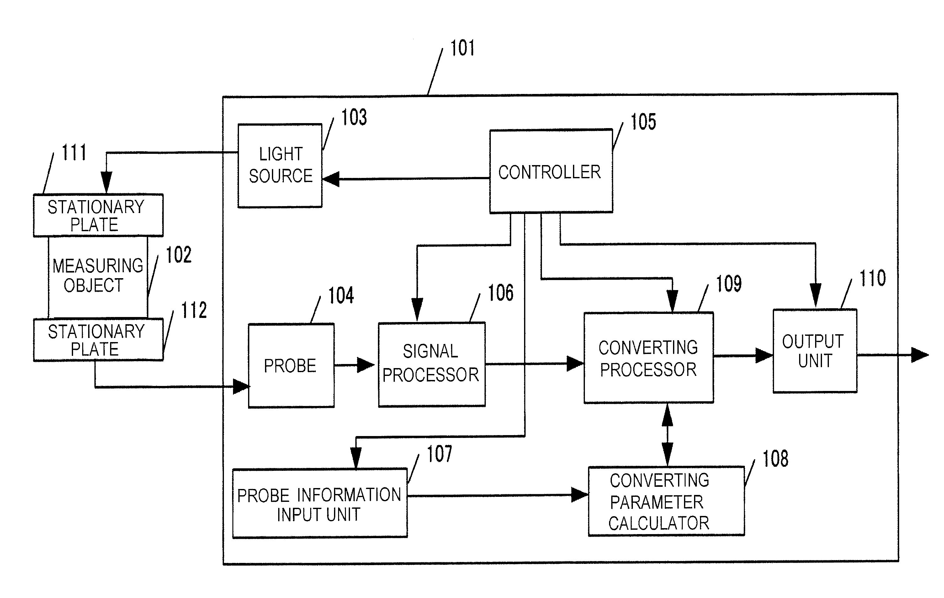
[0042]FIG. 1 is a block diagram depicting a biological information processing apparatus 101 of Example 1. The biological information processing apparatus of Example 1 uses a photoacoustic tomography technology. In FIG. 1, a measuring object 102 is an object to be measured, and is a part of a body of a subject person, for example. The measuring object 102 is a subject of the present invention. A light source 103 is a pulse laser light source for generating a photoacoustic wave from the measuring object 102. The light source 103 corresponds to an acoustic wave generator. A probe 104 is a transducer which converts a photoacoustic wave generated from the measuring object 102 into an electric signal, and a controller 105 controls operation timing of each block.

[0043]A signal processor 106 is an electric circuit which receives and processes an electric signal from the probe 104, and inputs the processed electric signal into a converting processor 109, and is comprised of an application ci...

example 2

[0086]Now Example 2 will be described. The difference of Example 2 from the above mentioned Example 1 is that a probe ID number is input as the probe characteristic information on the probe.

[0087]In the block configuration in FIG. 1, operations of the measuring object 102, light source 103, probe 104, signal processor 106, converting processor 109, output unit 110, stationary plate 111 and stationary plate 112 are the same as Example 1, therefore description thereof is omitted.

[0088]The differences from Example 1 are as follows: a method of the controller 105 controlling operation timing of each portion; the probe information input unit 107 inputting a probe ID number as the characteristic information of the probe; and a method of the converting parameter calculator 108 calculating converting parameters.

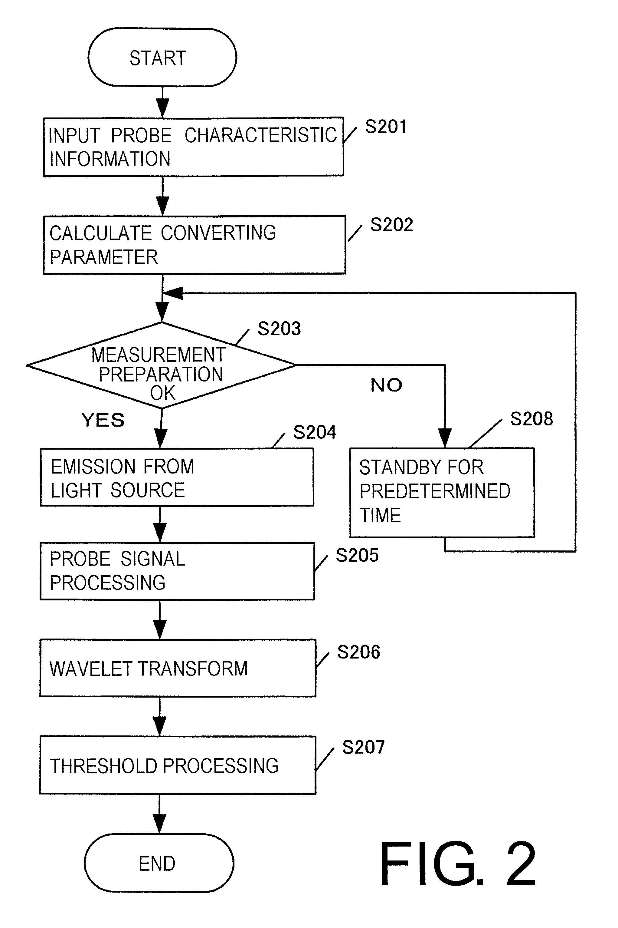
[0089]The difference of the processing flow executed by the controller 105, compared with Example 1, will be described with reference to FIG. 2.

[0090]In step S201, the probe informat...

example 3

[0097]Now Example 3 will be described. The difference of Example 3 from Example 1 is that the probe characteristic information is not input from the outside, but is calculated within the apparatus.

[0098]FIG. 9 is a block diagram depicting a biological information processing apparatus 901 of Example 3. Description on a measuring object 902, light source 903, probe 904, signal processor 906, converting parameter calculator 908, converting processor 909, output unit 910 and stationary plates 911 and 912, which is the same as Example 1, is omitted.

[0099]A controller 905 is a controller which controls operation timing of each portion. A difference from the controller of Example 1 is that the light source 903 and the probe information calculator 907 are controlled before measurement, and the probe characteristic information is calculated internally. In other words, in the case of Example 1, the probe characteristic information is input from the outside in step S201 in FIG. 2, but in this ...


PUM


Abstract

Provided is a technology for improving accuracy of noise elimination by a wavelet transform. The present invention is a subject information processing apparatus including: an acoustic wave generator which generates an acoustic wave from a subject; a probe which receives the acoustic wave and converts the received acoustic wave into an electric signal; a converting processor which determines a wavelet coefficient string by performing the wavelet transform on the electric signal; and a threshold processor which eliminates wavelet coefficients smaller than a predetermined threshold out of the wavelet coefficient string, wherein the converting processor selects a coefficient string corresponding to a mother wavelet of which degree of similarity with an impulse response waveform of the probe is highest, out of coefficient strings corresponding to a plurality of mother wavelets stored in advance, and performs the wavelet transform.

Description

BACKGROUND OF THE INVENTION[0001]1. Field of the Invention[0002]The present invention relates to a subject information processing apparatus, a subject information processing method and a subject information processing program for receiving acoustic waves emitted from a subject.[0003]2. Description of the Related Art[0004]A lot of research has been ongoing in medical fields related to technologies for imaging a form and function of internal tissues by irradiating an acoustic wave, pulse laser beam or the like, onto a subject, which is a measuring object, and receiving and processing acoustic waves emitted from inside the measuring object. For example, there is an apparatus using an ultrasonic echo technology which irradiates an ultrasonic wave, which is an acoustic wave, onto a biological tissue, and receives the reflected ultrasonic wave (acoustic wave). There is also an apparatus using photoacoustic tomography (PAT), which irradiates light onto a biological tissue, and receives a p...

Claims


Application Information

Patent Timeline
Patent Type & Authority Applications(United States)
IPC IPC(8): G06F19/00
CPCA61B5/0059A61B5/0095A61B5/7203G06K9/00516A61B8/5215G01S7/52077G01S15/8977A61B5/726G16H50/20G06F2218/06
Inventor SUZUKI, KOICHI
Owner CANON KK
Why Eureka
Try Eureka