Control device of hybrid vehicle

a control device and hybrid vehicle technology, applied in the direction of electric devices, machines/engines, transportation and packaging, etc., can solve the problems of inability to continue operation disabled regions, and inability to protect motors near the highest vehicle speed of vehicle performance, etc., to achieve compact structure, simplify cooling system, and reduce costs

Inactive Publication Date: 2011-09-29
AISIN AW CO LTD
View PDF2 Cites 25 Cited by
  • Summary
  • Abstract
  • Description
  • Claims
  • Application Information

AI Technical Summary

Benefits of technology

[0007]It is an object of the present invention to provide a control device of a hybrid vehicle, which is capable of protecting a motor while implementing cost reduction and a compact structure by simplifying a cooling system and reducing the size of the motor.
[0008]In the present invention according to a first aspect, a motor protection control unit reduces a rotational speed of an engine when a temperature of a motor reaches an upper threshold value or more while the motor is being rotated at a predetermined rotational speed or more by driving rotation of the engine and is being controlled to zero torque. Thus, a rotational speed of the motor can be reduced, and an amount of heat generation by the zero torque control can be reduced, whereby the temperature of the motor can be reduced, and the motor can be protected. This can eliminate the need to improve performance of a cooling structure of the motor, and to increase the size of the motor, whereby cost reduction and a compact structure of a hybrid vehicle can be implemented.
[0009]In the present invention according to a second aspect, the upper threshold value is set to be lower as the rotational speed of the motor becomes higher. This can prevent the temperature of the motor from increasing excessively according to the rotational speed of the motor, whereby the motor can be reliably protected.
[0010]In the present invention according to a third aspect, when the rotational speed of the engine is reduced by the motor protection control unit, the vehicle speed maintaining control unit shifts the speed ratio of the speed change mechanism toward a higher speed according to reduction in the rotational speed of the engine. This can prevent a vehicle speed from reducing with the reduction in the rotational speed of the engine.
[0011]In the present invention according to a fourth aspect, when the rotational speed of the engine is reduced by the motor protection control unit, the driving force maintaining control unit increases output torque of the engine so as to maintain a driving force that is transmitted to a driving wheel. This can prevent a vehicle speed from reducing due to a reduction in the driving force that is transmitted to a driving wheel.
[0012]In the present invention according to a fifth aspect, the motor is coupled to an input shaft of the speed change mechanism via a deceleration mechanism. Thus, although the output torque of the motor can be amplified and transmitted to the driving wheel, the motor rotates at a higher speed as compared to the rotational speed of the engine. However, since the motor protection control unit reduces the rotational speed of the engine when the temperature of the motor reaches the upper threshold value or more, the rotational speed of the motor can be significantly reduced, whereby the motor can be reliably protected.

Problems solved by technology

If the amount of heat generation is larger than the amount of heat dissipation, the temperature of the motor can exceed the heat-resistant temperature, and thus the motor is in a continuous operation disabled region in which the motor cannot be continuously operated.
However, the continuous operation disabled region is a problem that occurs near the highest vehicle speed of the vehicle performance.
Accordingly, the structure of such a hybrid drive device is not necessarily preferable for use in relatively inexpensive, small vehicles as described above.
However, the motor cannot be protected near the highest vehicle speed of the vehicle performance, if cost reduction and a compact structure are implemented by merely simplifying the cooling system and reducing the size of the motor.

Method used


Image

  • Control device of hybrid vehicle
  • Control device of hybrid vehicle
  • Control device of hybrid vehicle

Examples


Embodiment Construction

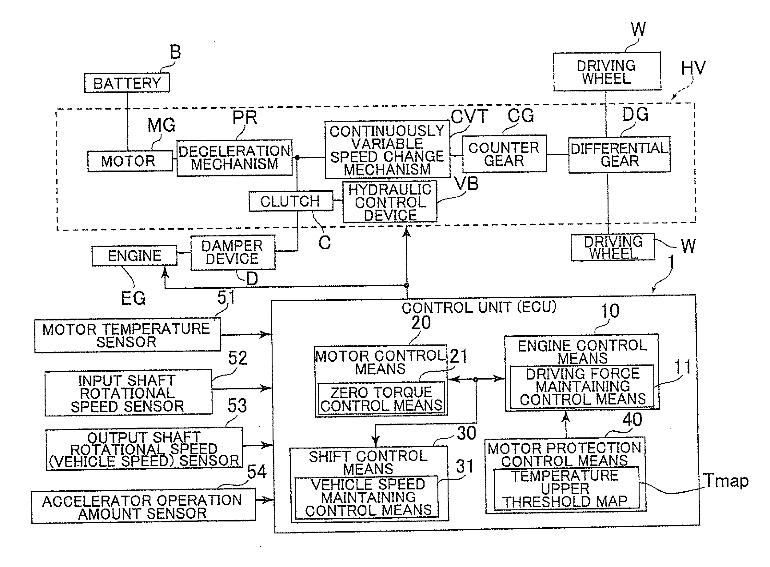
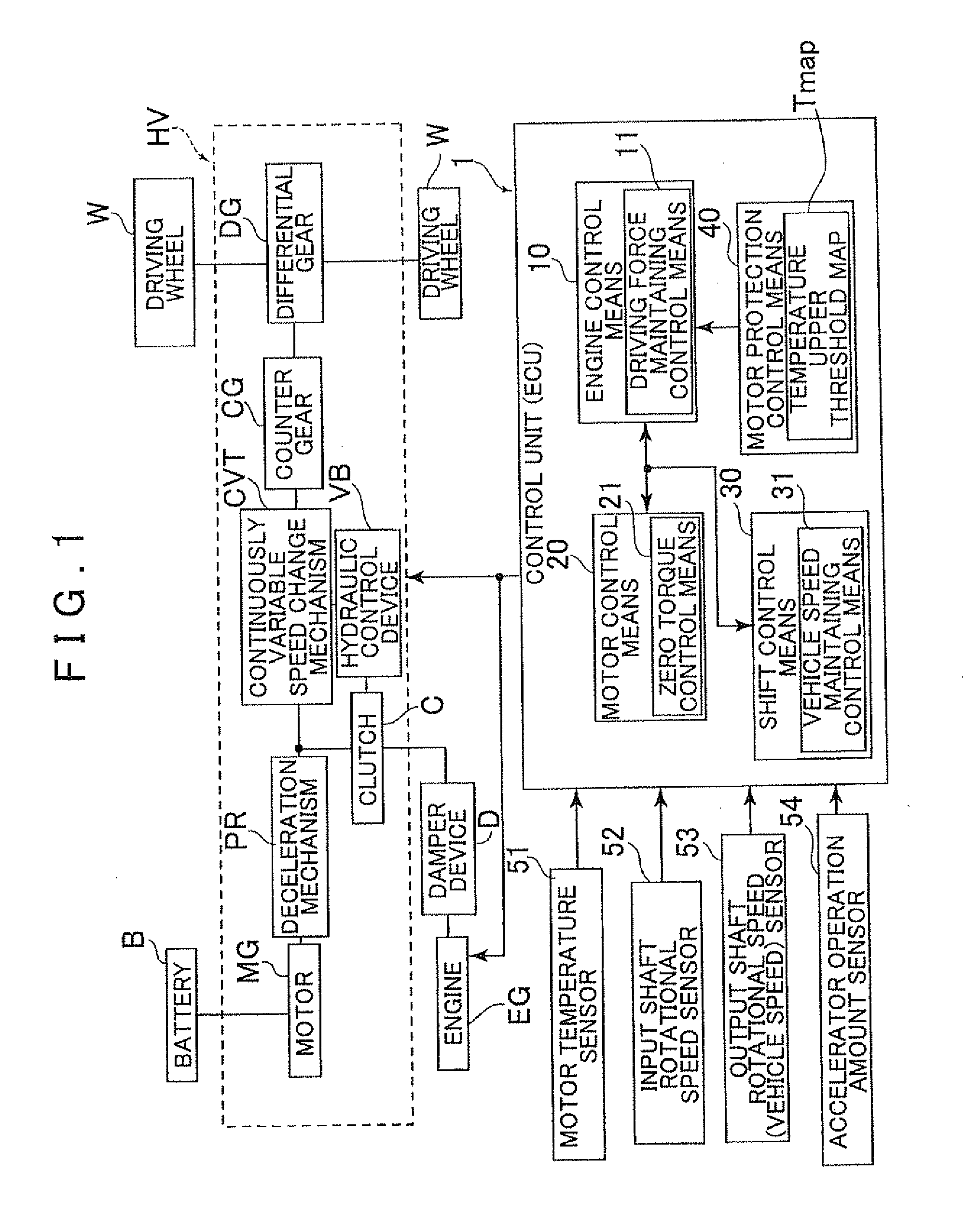
[0019]An embodiment of the present invention will be described below with reference to FIGS. 1 to 6. First, the general structure of a hybrid vehicle (a hybrid drive device HV) to which the present invention can be applied will be described with reference to FIG. 1.

[0020]As shown in FIG. 1, the hybrid vehicle to which the present invention can be applied is preferably used in, e.g., a front engine front drive (FF) type, and an engine EG is connected to the input side of the hybrid drive device HV via a damper device D, and the output side of the hybrid drive device HV is connected to right and left driving wheels W. The hybrid drive device HV includes a motor MG, a deceleration mechanism PR, a clutch C, a continuously variable speed change mechanism (a speed change mechanism) CVT, a hydraulic control device VB, a counter gear CG, a differential gear DG, and the like.

[0021]The motor MG is connected to a battery B, and the motor MG is connected to, e.g., an input shaft of the belt typ...


PUM


Abstract

A control device of a hybrid vehicle, configured with an engine; a motor that rotates together with the engine at least during traveling by using a driving force of the engine, and a speed change mechanism that shifts rotation of the engine and the motor to transmit the shifted rotation to a driving wheel. A zero torque control unit controls output torque of the motor to zero torque when a rotational speed of the motor reaches a predetermined rotation speed or more by driving rotation of the engine, and a motor temperature detection unit that detects a temperature of the motor. A motor protection control units that reduces a rotational speed of the engine when the temperature of the motor reaches an upper threshold value or more while the motor is being rotated at the predetermined rotational speed or more by the driving rotation of the engine.

Description

INCORPORATION BY REFERENCE[0001]The disclosure of Japanese Patent Application No. 2010-069162 filed on Mar. 25, 2010 including the specification, drawings and abstract is incorporated herein by reference in its entirety,BACKGROUND OF THE INVENTION[0002]The present invention relates to a control device that is mounted on, e.g., a hybrid vehicle, and more particularly to a control device of a hybrid vehicle, which controls output torque of a motor to zero torque when the rotational speed of the motor that operates together with an engine reaches a predetermined speed or more during traveling by using a driving force of the engine.DESCRIPTION OF THE RELATED ART[0003]In recent years, various hybrid drive devices with improved fuel economy are proposed to address environmental issues, etc. One of such hybrid drive devices is a hybrid drive device in which a motor (a rotational electrical machine MG) is rotated together with an input shaft of a speed change mechanism (see Japanese Patent ...

Claims


Application Information

Patent Timeline
Patent Type & Authority Applications(United States)
IPC IPC(8): B60W20/00B60W10/06B60W10/08B60K6/48B60K6/543B60L15/20B60W10/10F02D29/02F16H59/78F16H61/02F16H61/662F16H61/684F16H63/50
CPCB60K6/48Y02T10/7258B60L2240/425B60W10/06B60W10/08B60W10/11B60W20/00B60W2510/087B60W2710/0644F16H59/78F16H2061/0232Y02T10/6221Y02T10/6286Y02T10/642B60L3/04Y02T10/62Y02T10/64Y02T10/72B60W20/10
Inventor NOMURA, MASAKIKIOKA, HIROAKITAKEDA, KENCHINEN, SHINTARO
Owner AISIN AW CO LTD
Why Eureka
Try Eureka