Eureka AIR delivers breakthrough ideas for toughest innovation challenges, trusted by R&D personnel around the world.

Method for manufacturing honeycomb structure forming die

Active Publication Date: 2011-09-29
NGK INSULATORS LTD
View PDF5 Cites 11 Cited by
  • Summary
  • Abstract
  • Description
  • Claims
  • Application Information

AI Technical Summary

Benefits of technology

[0009]The present invention aims to provide a method for manufacturing a honeycomb structure forming die, the method enables to more easily manufacture a die for extrusion-forming a honeycomb structure having cells having different sizes.
[0014]In a method for manufacturing a honeycomb structure forming die of the present invention, since a die is formed with forming processing liquid grooves and allowing the processing liquid to flow though the grooves, the processing stability of a die for extrusion-forming a honeycomb structure having cells having different sizes can be improved, and the die can be manufactured more easily.

Problems solved by technology

There is a problem that, as the exhaust gas flows in the DPF, the particulate matter contained in the exhaust gas deposits in the one side end portion (exhaust gas inflow side end portion) to clog a cell.
This is prone to be caused in the case that a large amount of particulate matter is contained in the exhaust gas or in a cold district.
When a cell is thus clogged, there arises a problem that the pressure loss in the DPF is rapidly increased.
However, in a honeycomb structure having different cell sizes between the target fluid inflow side and the outflow side, since cells having different cell sizes are aligned, the partition walls are not linearly formed.
However, since many steps are required for manufacturing a mesh-shaped electrode and a DPF has a large diameter, time of several months to half year is required for manufacturing an electrode for manufacturing a die.
Since a sludge generation amount is increased according to the increase in the processing removal amount, in a method where liquid holes are formed and where a processing liquid is allowed to flow through the liquid holes (see JP-A-2005-254345), machining removal is difficult because the flow rate of the processing liquid is not sufficient.
This causes deterioration in processing stability and accuracy of slit width / depth of the slits.
In addition, since the liquid holes are formed with a laser or a drill, processing stability of the slits deteriorates by the influences of dross and burr.

Method used


Image

  • Method for manufacturing honeycomb structure forming die
  • Method for manufacturing honeycomb structure forming die
  • Method for manufacturing honeycomb structure forming die

Examples


example

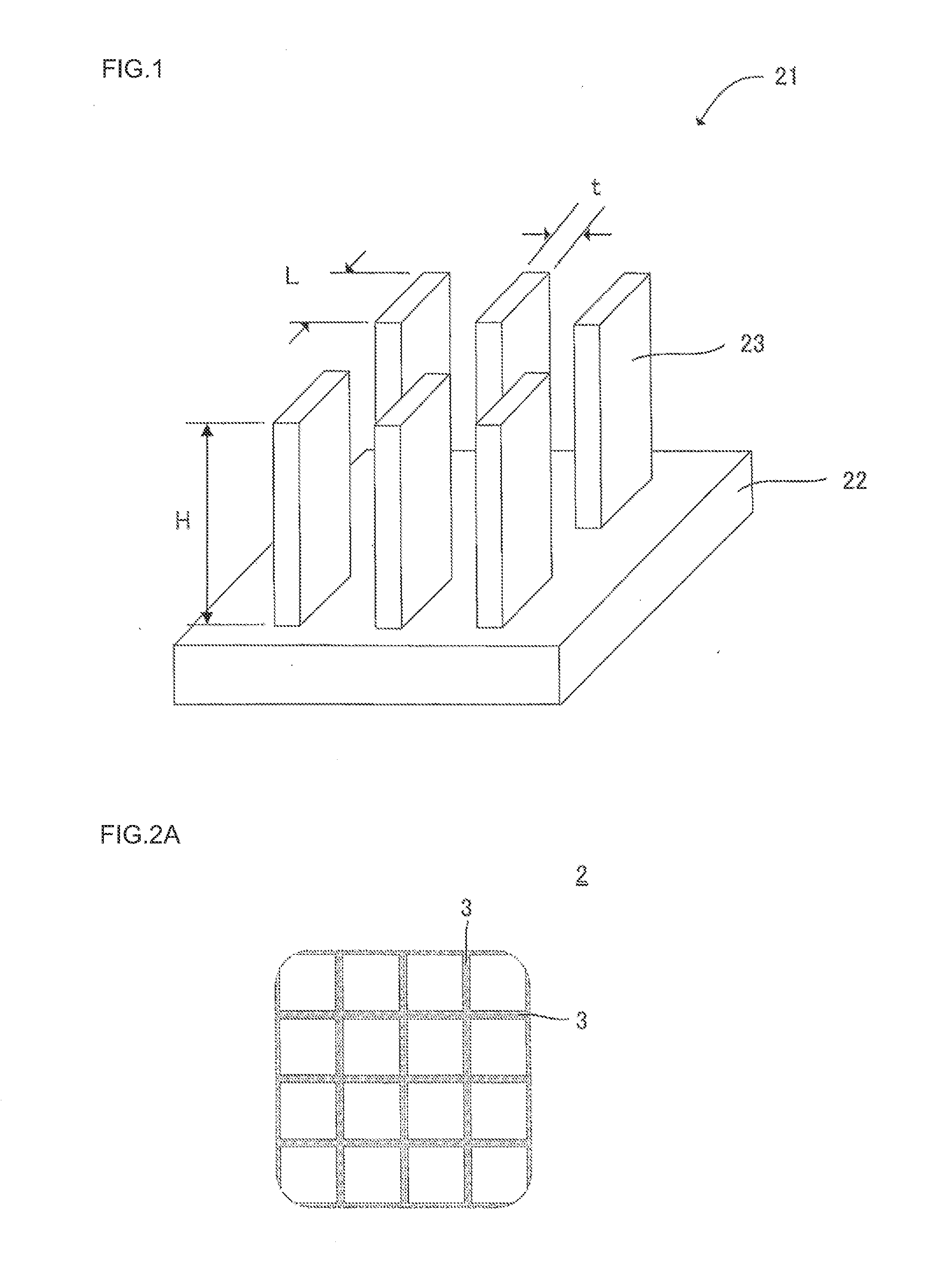
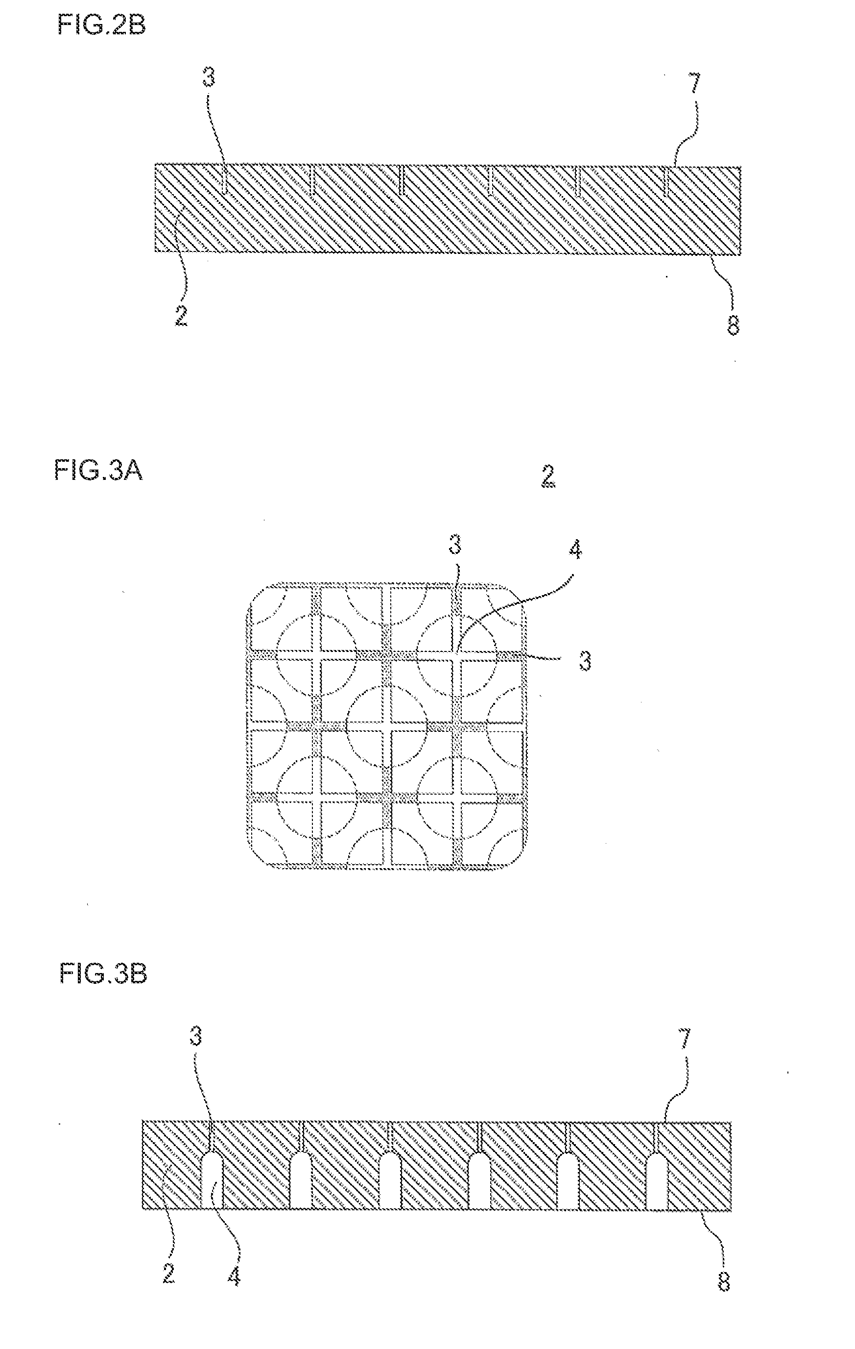
[0060]In the processing liquid groove forming step, there were formed, as shown in FIGS. 2A and 2B, processing linear liquid grooves 3 having a width of 0.18 mm, which is smaller than that of the slits 5, on the one side end face 7 of the die substrate 2 where slits 5 are planned to be formed of the stainless steel plate-shaped die substrate 2 having vertical and horizontal sizes of 180×180 mm and a thickness of 20 mm.

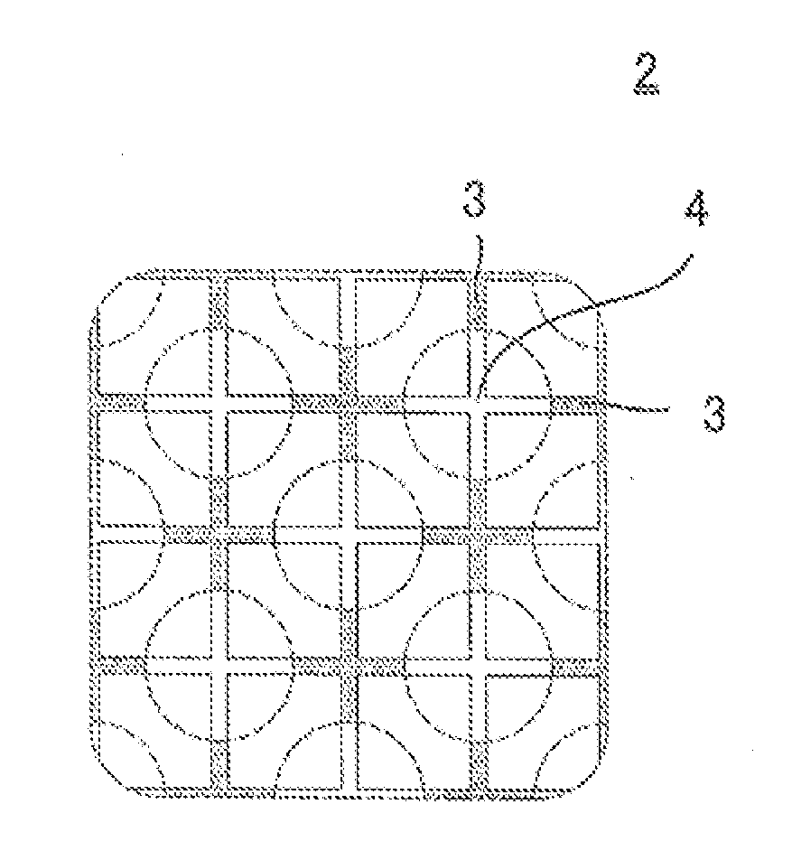
[0061]Next, in the introduction hole forming step, about 10 thousands of introduction holes 4 having an opening diameter of 1.4 mm was formed in the other side end face 8 of the die substrate 2 as shown in FIGS. 3A to 3C in positions corresponding with vertexes of the cells 42 of the honeycomb structure 40 to be obtained by extrusion forming up to the depth of 17.5 mm from the kneaded clay introduction face 18.

[0062]Next, comb-like electro-discharge machining was performed as shown in FIGS. 4A to 4C. Specifically, the plate-shaped protrusion electrodes 23 provided on t...


PUM

PropertyMeasurementUnit
Widthaaaaaaaaaa

Abstract

There is provided a method for manufacturing a honeycomb structure forming die including a liquid groove forming step for forming linear processing liquid grooves 3 whose width is smaller than that of the slit 5, in positions for forming the slits 5 for forming the partition walls 41 of the honeycomb structure 40 by subjecting the kneaded clay to extrusion in one side end face 7 as a kneaded clay forming face 17 of a plate-shaped die substrate 2. An introduction hole forming step for forming introduction holes 4 for introducing the kneaded clay is performed before or after the liquid groove forming step. Slits 5 communicating with the introduction holes 4 are formed by performing comb-like electro-discharge machining by a comb-like electrode 21 where plate-shaped protrusion electrodes 23 corresponding with the slit 5 width are disposed in positions including the processing liquid grooves 3.

Description

BACKGROUND OF THE INVENTION AND RELATED ART STATEMENT[0001]The present invention relates to a method for manufacturing a honeycomb structure forming die for extrusion-forming a honeycomb structure having cells having different sizes.[0002]There is increasing the need for removing particulate matter and harmful substances in exhaust gas from internal combustion engines, boilers, and the like in consideration of influences to an environment. In particular, regulations regarding the removal of Particulate matter (hereinbelow sometimes referred to as “PM”) discharged from diesel engines tend to be strengthened on a global basis, and the use of a honeycomb filter is attracting attention as a trapping filter (hereinbelow sometimes referred to as “DPF”) for removing PM. Therefore, various systems have been proposed. In the aforementioned DPF generally has a structure where a plurality of cells having a cross sectional shape of a quadrangle, hexagon, or the like and functioning as fluid pas...

Claims


Application Information

Patent Timeline
IPC IPC(8): B23H1/04
CPCB23P15/243B28B3/269B23H2200/30B23H1/04B28B7/346
Inventor HAYASHI, SEIICHIRONAGAE, TOMOKIIWADE, MASANARIHOSOKAWA, HIROFUMI
Owner NGK INSULATORS LTD
Why Eureka
Eureka Blog
Learn More