Imaging apparatus

Active Publication Date: 2011-09-29
PANASONIC LIQUID CRYSTAL DISPLAY CO LTD +1
View PDF3 Cites 48 Cited by
  • Summary
  • Abstract
  • Description
  • Claims
  • Application Information

AI Technical Summary

Benefits of technology

[0010]To solve the above problem, the inventor has made an optical system, which can be released from a mold without difficulty and can be comparatively simply manufactured, and which has a focusing effect of light from an object and a shielding effect for large incident angle light. The subject matter of the present invention is to provide a pre-focus micro lens array and an aperture array oppositely to each other, provide an aperture of the aperture array in the vicinity of the first focus of the light from the object by the pre-focus micro lens array, and to perform the secondary light focusing with a post-focus micro lens array at the same time. The large incident angle light to the image sensor is shielded with the pre-focus micr

Problems solved by technology

However, in this method, downsizing and thinning of the apparatus are limited.
This method has a problem that a finger vein or the like cannot be resolved without blocking light at a large incident angle among light incident on the respective pixels.
The finger vein authentication apparatus using transmission light has a problem that the apparatus scale is larger than that of the apparatus using scattered light.
This structure cannot be applied to a thin type

Method used


Image

  • Imaging apparatus
  • Imaging apparatus
  • Imaging apparatus

Examples


Example

First Embodiment

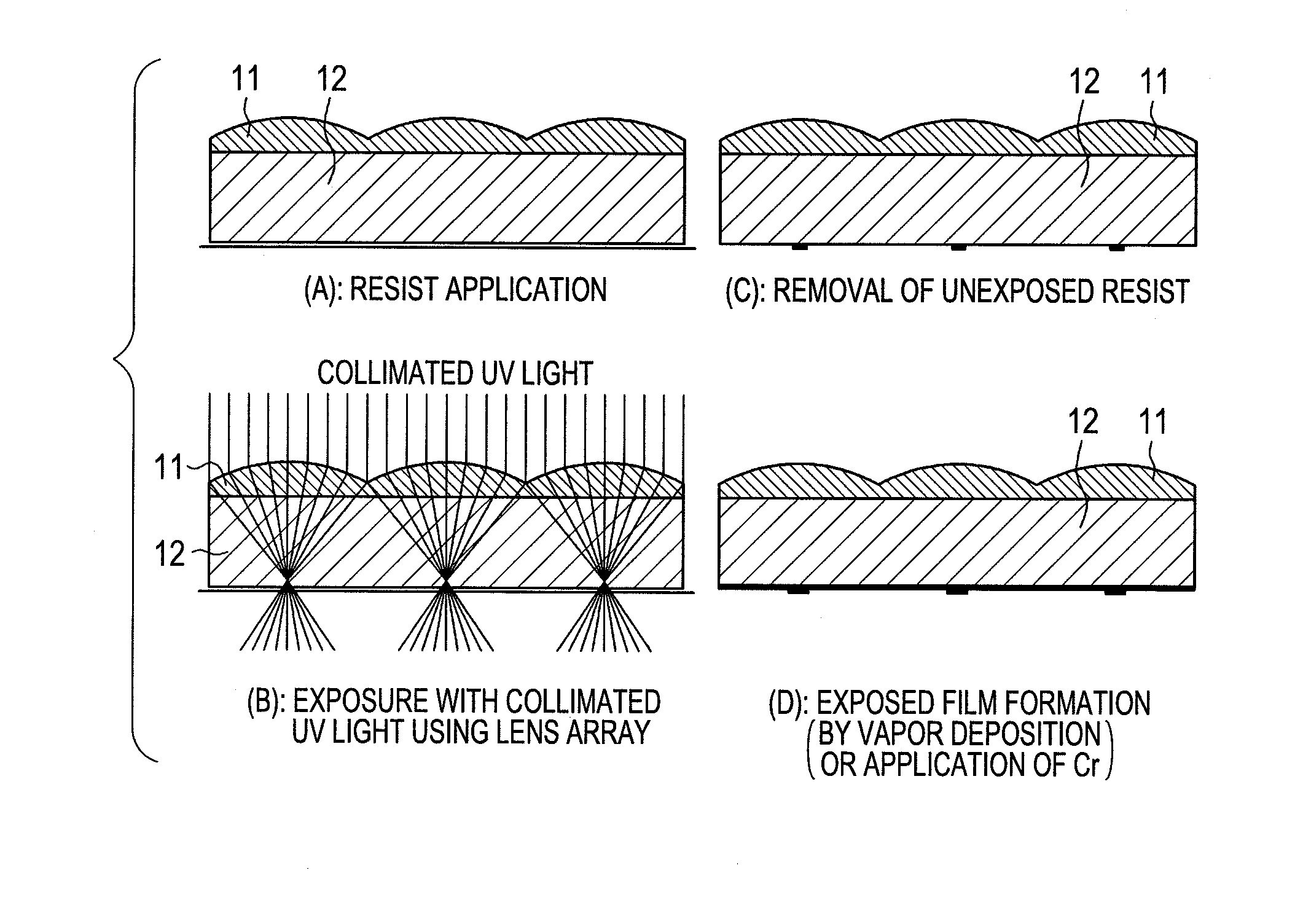
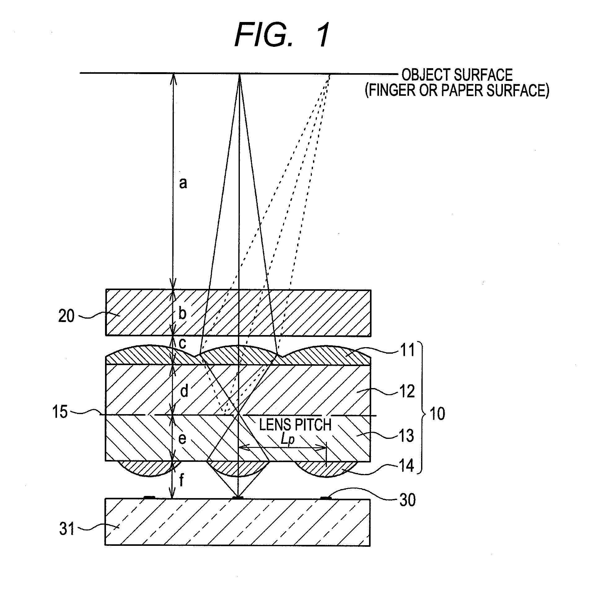
[0038]FIG. 1 schematically shows a first embodiment of the present invention and its principle. Note that although not shown in FIG. 1, when the imaging apparatus is used as a finger vein authentication apparatus as in the case of FIG. 23, a light source such as an LED to emit a near infrared ray from the image sensor side toward a finger is required. The light scattered in the finger is utilized for finger vein authentication. It is considered that the object surface in the case of the imaging apparatus in FIG. 1 is biological tissues in the finger, that in the case of a finger print authentication apparatus is a finger surface, and that in the case of a facsimile machine is a paper surface.

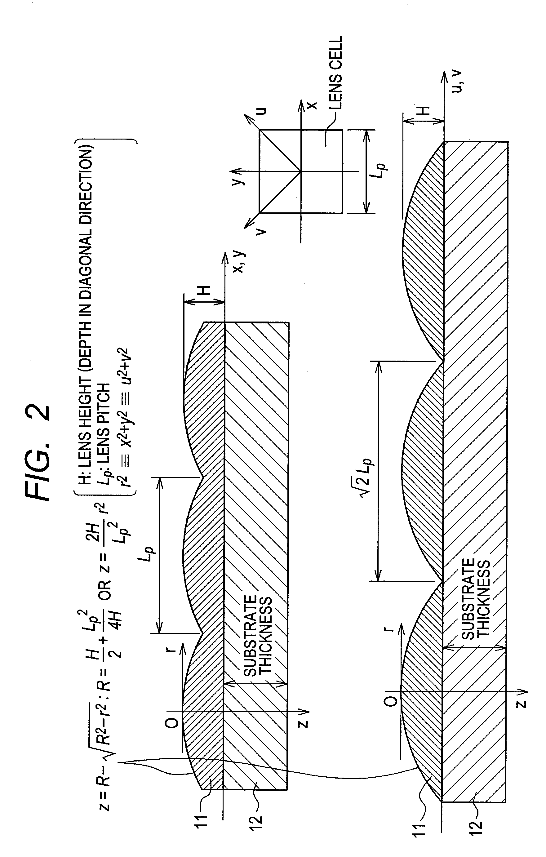
[0039]The near infrared ray and ordinary light (extraneous light) scattered from the object surface arrive at a light focusing / shielding array plate 10 through a visible light cut-off filter 20 having a thickness b provided away by distance a and an air layer. The light focusing / ...


PUM


Abstract

An imaging apparatus is realized which enables a thin finger vein authentication apparatus having a thickness installable in a portable information device. A light beam emitted from an object passes through a visible light cut-off filter 20 and enters a pre-focus lens array 11. The pre-focus lens array 11 focuses the light beam on an opening of a micro aperture array 15. The light beam passed through the micro aperture array 15 diverges, but it is focused with the post-focus lens array 13 on the light detection device 30. With this structure, a thin imaging apparatus can be obtained with maintained resolution, and a finger authentication apparatus installable in a portable information device can be realized.

Description

CLAIM OF PRIORITY[0001]The present application claims priority from Japanese Patent Application JP 2010-067960 filed on Mar. 24, 2010, the content of which is hereby incorporated by reference into this application.BACKGROUND OF THE INVENTION[0002]The present invention relates to an imaging device applicable to mobile device information security and a finger vein authentication apparatus using the imaging device.DESCRIPTION OF RELATED ART[0003]In recent years, to ensure information security in mobile information devices, biometrics authentication is very important. For example, in a biometric authentication apparatus using finger vein authentication, imaging is mainly performed by projecting an image onto an image sensor with a set of optical lenses. However, in this method, downsizing and thinning of the apparatus are limited.[0004]On the other hand, for downsizing and thinning of the apparatus to a large extent, biometrics imaging with a micro lenses corresponding to respective pix...

Claims


Application Information

Patent Timeline
IPC IPC(8): H01L27/146B23P11/00
CPCY10T29/49826H01L27/14685H01L27/14625
Inventor OKU, KENTARO
Owner PANASONIC LIQUID CRYSTAL DISPLAY CO LTD
Why Eureka
Try Eureka