Battery charging apparatus

a charging apparatus and battery technology, applied in the field of battery charging apparatus, can solve the problems of large-scale battery charging of high-capacity driving batteries simply using household commercial power, limited maximum power available from commercial power outlets, etc., and achieves rapid charging, short time, and improved reliability.

Inactive Publication Date: 2011-09-29
SANYO ELECTRIC CO LTD
View PDF2 Cites 28 Cited by
  • Summary
  • Abstract
  • Description
  • Claims
  • Application Information

AI Technical Summary

Benefits of technology

[0011]To achieve the objects described above, the battery charging apparatus for the first aspect of the present invention is a charging apparatus to charge an externally connected load battery. The battery charging apparatus can be provided with an auxiliary battery that can be charged, a first charging circuit that can charge the auxiliary battery with a first charging current derived from an externally connected commercial power source, and a second charging circuit that can charge the load battery with a second charging current that is higher than the first charging current and is derived from power from the auxiliary battery, which is charged by the first charging circuit. The first charging circuit can be connected to allow power supply to the auxiliary battery and...

Problems solved by technology

Consequently, battery chargers with enough capacity and charging capability to charge the batteries in those vehicles have inevitably become large-scale.
Attempting to charge these types of high-capacity driving batteries simply using household commercial power is problematic due to the considerable charging time required.
This is because the maximum power available from a commercial power outlet is limited.
For example, the maximum usable power available from a 200V single-phase commercial power outlet is limited to approximately 5 KW (in Japan).
This has the drawback that the required operator confirmation and switching operations are troublesome.
However, to determine the timer settings for switching the auxiliary battery between charging and discharging, computations based on auxiliary and driving battery remaining ...

Method used


Image

  • Battery charging apparatus
  • Battery charging apparatus
  • Battery charging apparatus

Examples


first embodiment

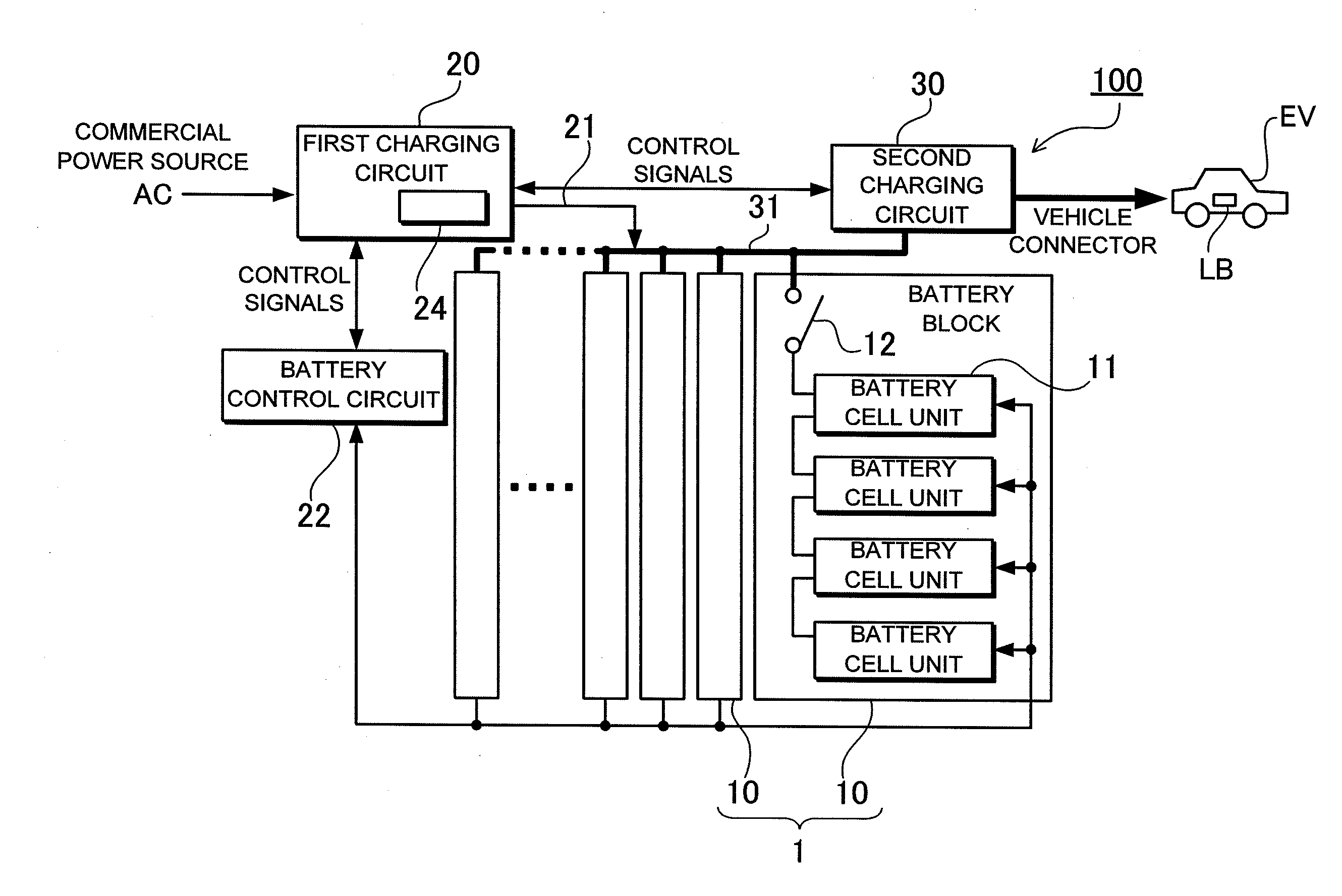
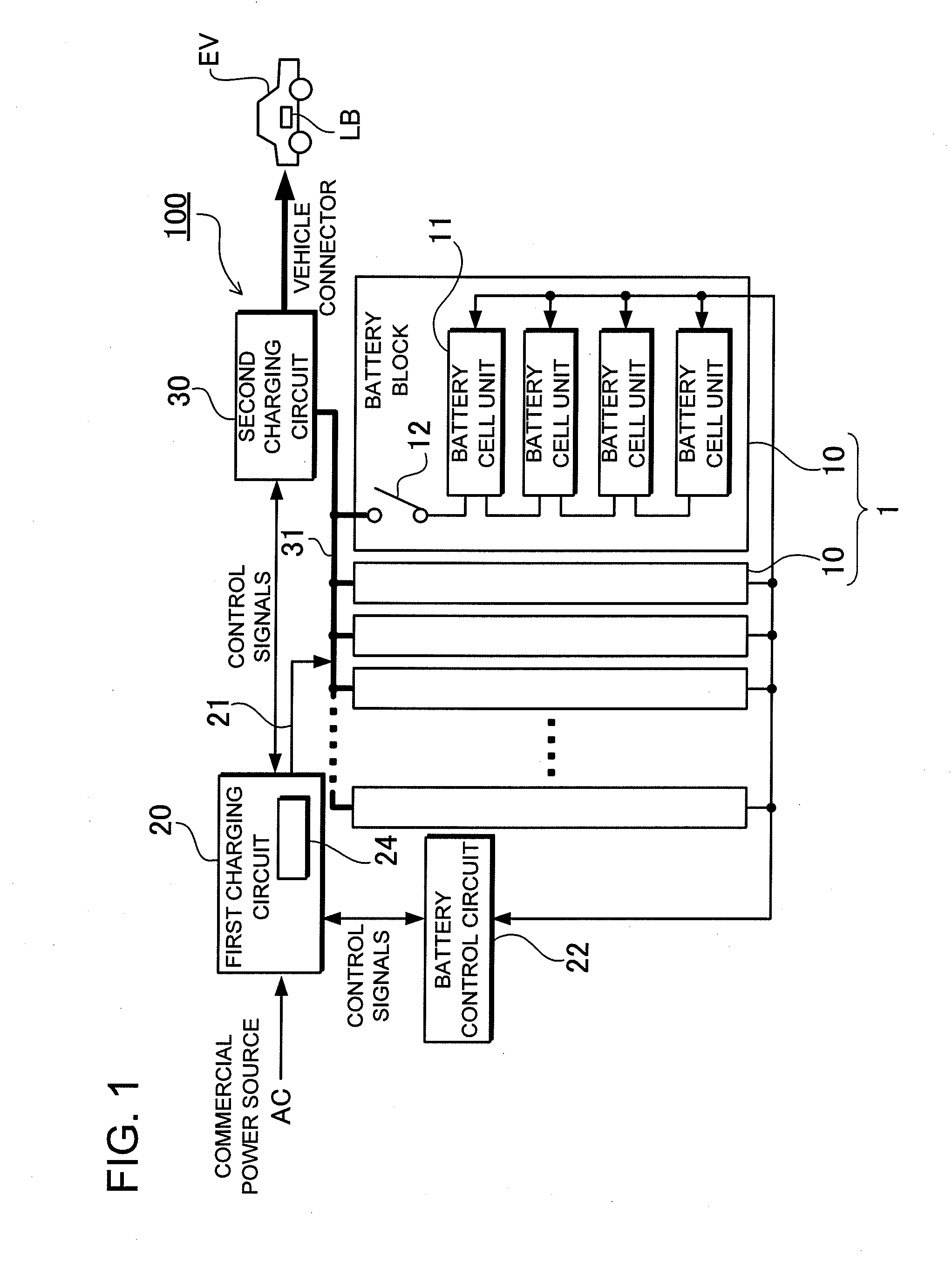
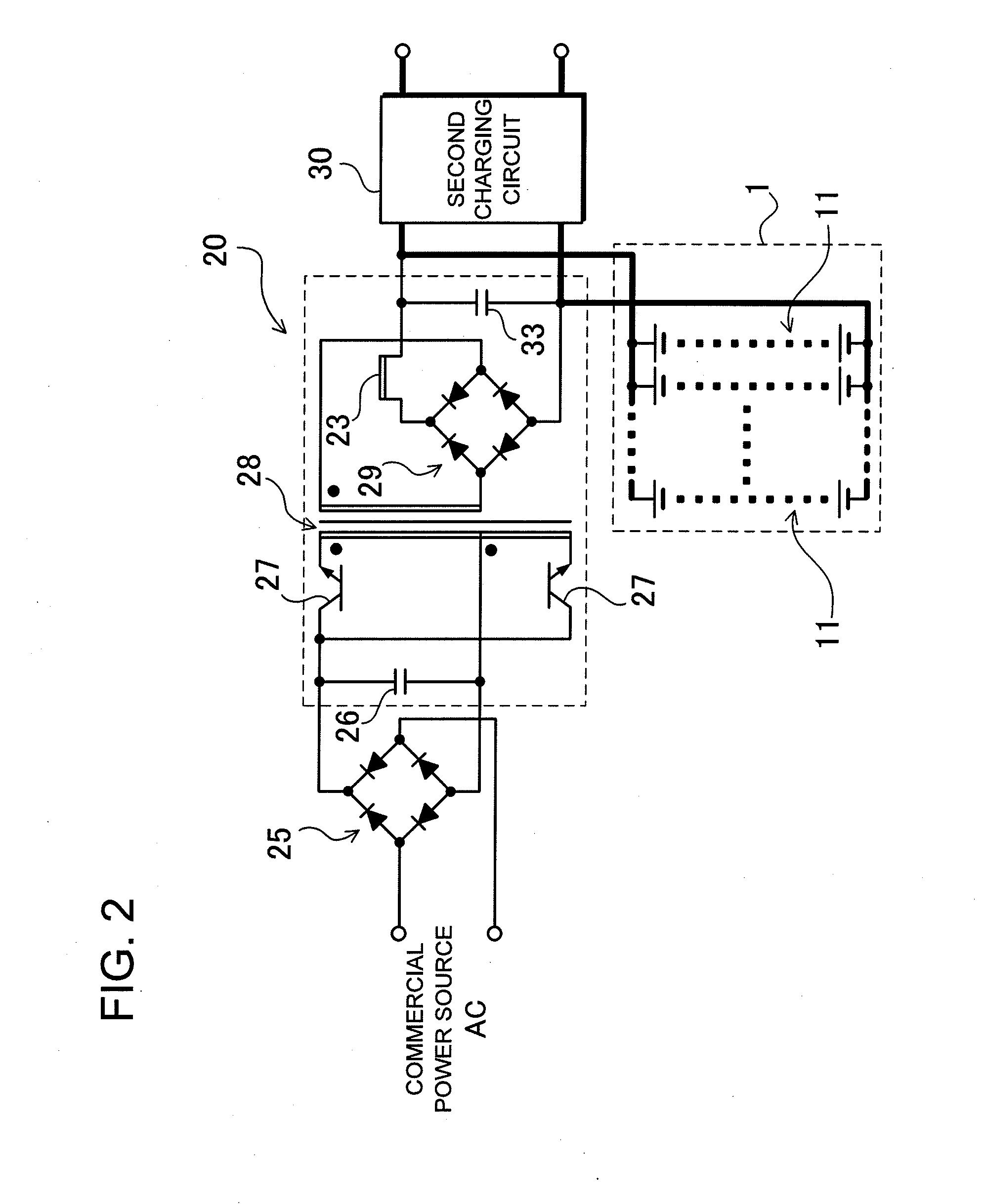
[0035]FIGS. 1 and 2 show a battery charging apparatus for the first embodiment of the present invention. FIG. 1 is a schematic diagram showing the battery charging apparatus 100, and FIG. 2 is a circuit diagram showing an example of the first charging circuit 20 in FIG. 1. This embodiment illustrates power system architecture that uses commercial power available in the home to charge an auxiliary battery 1, and to charge an externally connected load battery LB. Here, charging of the driving battery in a vehicle EV such as plug-in hybrid vehicle or electric vehicle is described as an example of load battery LB charging. The battery charging apparatus 100 is provided with an auxiliary battery 1, a first charging circuit 20 that charges the auxiliary battery 1 from a commercial power source AC, a second charging circuit 30 that charges the load battery LB with the auxiliary battery 1, and a battery control circuit 22 that controls conditions for auxiliary battery 1 charging by the firs...

second embodiment

[0056]The embodiment above describes a system that uses commercial power as the only source of charging power. However, the present invention is not limited to that configuration and other sources of power can also be used in addition to, or in place of the commercial power source. For example, power generating systems that use renewable energy such as solar cells or fuel cells can be used as power sources. FIG. 3 shows a power source system employing a battery charging apparatus 200 for the second embodiment. In this figure, elements that are essentially the same as those in the first embodiment are labeled the same and their detailed description is omitted. Here, a system is described that combines an auxiliary battery 1 with a household power system, which has solar cells installed to power the household load HL or to sell power back to the electric company. This system makes possible operations that include using solar cell power to charge a load battery LB such as a vehicle dri...


PUM


Abstract

The battery charging apparatus has an auxiliary battery 1, a first charging circuit 20 for charging the auxiliary battery 1 with a first charging current derived from an externally connected commercial power source AC, and a second charging circuit 30 for charging the load battery LB with a second charging current that is higher than the first charging current and is derived from power from the auxiliary battery 1, which is charged by the first charging circuit 20. The first charging circuit 20 is connected to allow power supply to the auxiliary battery 1 and the second charging circuit 30. This makes charging circuit switching unnecessary and eliminates the need for components such as high-power switching devices. The charging apparatus has the positive features that stability and reliability are improved, and the load battery can be charged with the auxiliary battery 1 in a shorter time than using commercial power.

Description

BACKGROUND OF THE INVENTION[0001]1. Field of the Invention[0002]The present invention relates to charging apparatus that uses commercial power to charge a load battery such as a driving battery installed on-board a vehicle that supplies power to an electric motor to drive the vehicle.[0003]2. Description of the Related Art[0004]Along with widespread acceptance of vehicles such as hybrid vehicles driven by both an electric motor and an engine and electric vehicles driven only by an electric motor, battery chargers have become necessary to charge the driving batteries in those vehicles. In particular, high demand has recently developed for vehicles such as plug-in hybrid vehicles and electric vehicles carrying high-capacity driving batteries that have considerably more battery cells than those in a standard hybrid vehicle. Consequently, battery chargers with enough capacity and charging capability to charge the batteries in those vehicles have inevitably become large-scale. Attempting...

Claims


Application Information

Patent Timeline
IPC IPC(8): H01M10/46H02J7/00H02J7/34
CPCH02J7/0027Y02T10/7055H02J7/0055B60L11/1816Y02T90/14B60L2230/22Y02T10/7088Y02T10/7005Y02T90/121B60L11/1824B60L53/14B60L53/51H02J2207/40Y02T10/70Y02T10/7072Y02T90/12H02J7/0013H02J2310/48
Inventor FURUKAWA, KIMIHIKOTAIRA, SHIGEHARUITAGAKI, SHINICHISHOJI, YOSHIHIROMIYAZAKI, SHINYA
Owner SANYO ELECTRIC CO LTD
Why Eureka
Try Eureka