Despeckling laser-image-projection system

a laser and projection system technology, applied in the field of image projectors and handheld electronic devices, can solve the problems of speckle phenomenon, the display screen of a cell phone, a personal digital assistant (pda), or a portable media player is typically too small to present most documents in their original full-page format, etc., and achieves high optical throughput, high temporal/spatial stability of illumination patches, and high illumination homogeneity

Inactive Publication Date: 2011-09-29
ALCATEL LUCENT SAS
View PDF99 Cites 43 Cited by
  • Summary
  • Abstract
  • Description
  • Claims
  • Application Information

AI Technical Summary

Benefits of technology

[0008]Disclosed herein are various embodiments of a laser-image-projection system having (i) a fly's eye (FE) integrator including a plurality of lenslet pairs and (ii) a configurable optical diffuser, both located along an optical path between a laser and a spatial light modulator (SLM). In various embodiments, the optical diffuser introduces a temporally varying pattern of angular divergence into a laser beam directed toward the FE integrator for transmission to the SLM. In various embodiments, the FE integrator produces a plurality of illumination patches that are superimposed on the SLM in a manner that is substantially independent of the temporal variations introduced by the optical diffuser. Consequently, the regions of illumination produced by different pairs of opposing lenslets can overlap despite the presence of temporal variations in the angular divergence produced by the optical diffuser. Advantageously, the optical diffuser and FE integrator work together in a synergistic manner to enable the laser-image-projection system to be relatively compact and to provide relatively high illumination homogeneity across the SLM, relatively high temporal / spatial stability of the illumination patch, relatively high optical throughput between the laser and the projection screen, and relatively low speckle noise in the projected image.

Problems solved by technology

Some projectors employ laser light sources because the use of lasers enables creation of vibrant images with extensive color coverage that can be difficult to achieve with other (non-laser) light sources.
While the compactness of modern hand-held electronic devices is advantageous for portability purposes, their relatively small size, by its very nature, creates a disadvantage with respect to the display of visual information.
More specifically, the display screen of a cell phone, personal digital assistant (PDA), or portable media player is typically too small to present most documents in their original full-page format, or graphics and video content at their original resolution.
One significant obstacle to laser-image projection is the speckle phenomenon that tends to superimpose a granular structure on the perceived image.
However, the small size of a compact image projector makes it relatively difficult to incorporate an adequate despeckling functionality therein.

Method used


Image

  • Despeckling laser-image-projection system
  • Despeckling laser-image-projection system
  • Despeckling laser-image-projection system

Examples


Embodiment Construction

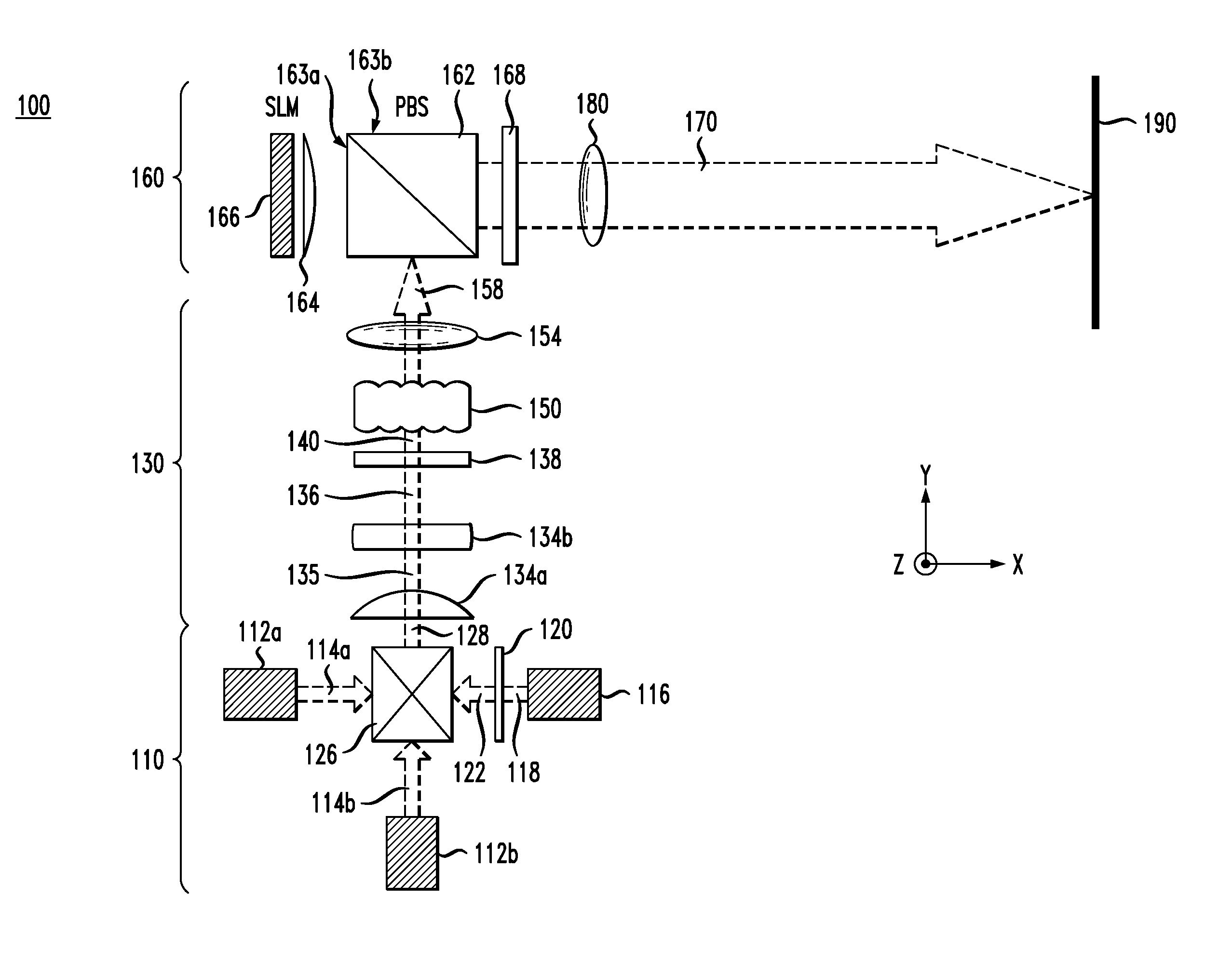
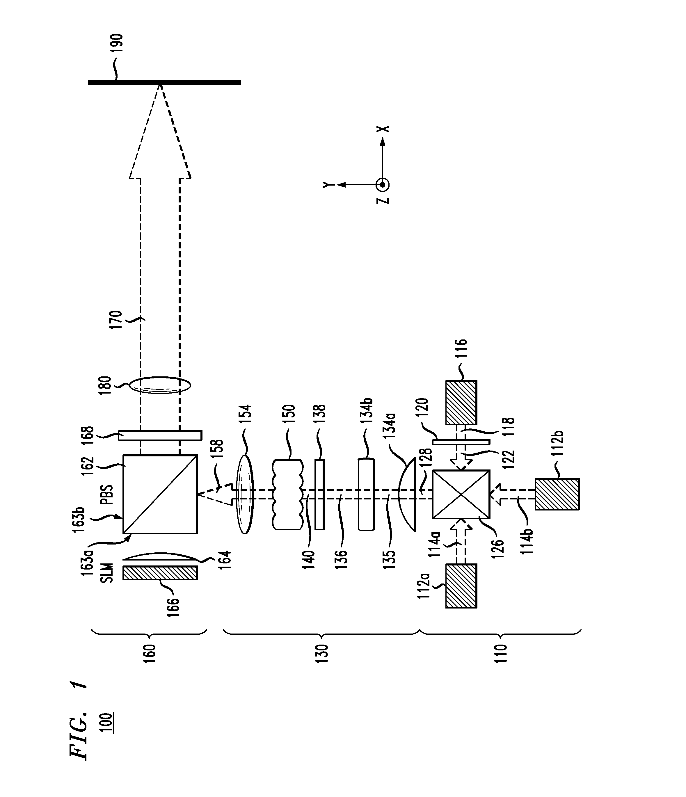
[0016]FIG. 1 shows a top view of a projector 100 according to one embodiment of the invention. Projector 100 has a laser light source 110 adapted to feed multi-colored light (e.g., red, green, and blue) through an optical beam-shaping (OBS) section 130 into a modulator section 160. Modulator section 160 generates a spatially intensity-modulated beam 170 that, after passing through a projection lens 180, forms a color image on a screen 190, which is not part of projector 100. In one embodiment, projection lens 180 is a compound lens comprising two or more individual lens pieces (not explicitly shown in FIG. 1). Although the term “screen” is used, it should be understood to include any suitable surface capable of supporting an image. For example, a screen can be an absorptive or reflective passive surface or active surface, such as a semiconductor surface, to enable further image processing.

[0017]Light source 110 has a set of three lasers 112a, 112b, and 116, each adapted to generate ...


PUM


Abstract

An optical device for projecting an image is disclosed. In one embodiment, the optical device includes a configurable optical diffuser adapted to produce a diffuse optical beam having a temporally varying pattern of angular divergence. The optical device further includes a plurality of lenslet pairs to shape the diffuse optical beam and a spatial light modulator to spatially modulate the shaped optical beam to project an image.

Description

BACKGROUND[0001]1. Field of the Invention[0002]The subject matter described herein relates generally to image projectors and hand-held electronic devices and, more specifically but not exclusively, to despeckling laser-image-projection systems.[0003]2. Description of the Related Art[0004]This section introduces aspects that may help facilitate a better understanding of the invention(s). Accordingly, the statements of this section are to be read in this light and are not to be understood as admissions about what is in the prior art or what is not in the prior art.[0005]A projector is a device that integrates a light source, optics, electronics, and a light-modulating element for the purpose of projecting an image or a sequence of images, e.g., from a computer or video input, onto a wall or screen for large-image viewing. There are many projectors available in the market, and they are differentiated by their size, resolution, performance, and other features. Some projectors employ las...

Claims


Application Information

Patent Timeline
Patent Type & Authority Applications(United States)
IPC IPC(8): G03B21/14
CPCH04N9/3161G03B21/14G02B27/48G03B21/208
Inventor RYF, ROLANDCHEN, GANG
Owner ALCATEL LUCENT SAS
Why Eureka
Try Eureka