Radiation imaging system and offset correction method thereof

Inactive Publication Date: 2011-09-29
FUJIFILM CORP
View PDF3 Cites 25 Cited by
  • Summary
  • Abstract
  • Description
  • Claims
  • Application Information

AI Technical Summary

Benefits of technology

[0019]In the present invention, the phase differential image is corrected on a segment-by-segment basis based on the offset value of the phase shift value. The offset value corresponds to the inclination angle of the second grating module relative to the scanning line. The offset values ar

Problems solved by technology

This causes a problem that a sufficient contrast cannot be obtained in the X-ray absorption image of living soft tissue or soft materials.
It is difficult, however, to produce a large concave grating in a single-piece.
It is unrealistic to provide the driving device to each of the grating modules

Method used


Image

  • Radiation imaging system and offset correction method thereof
  • Radiation imaging system and offset correction method thereof
  • Radiation imaging system and offset correction method thereof

Examples


Example

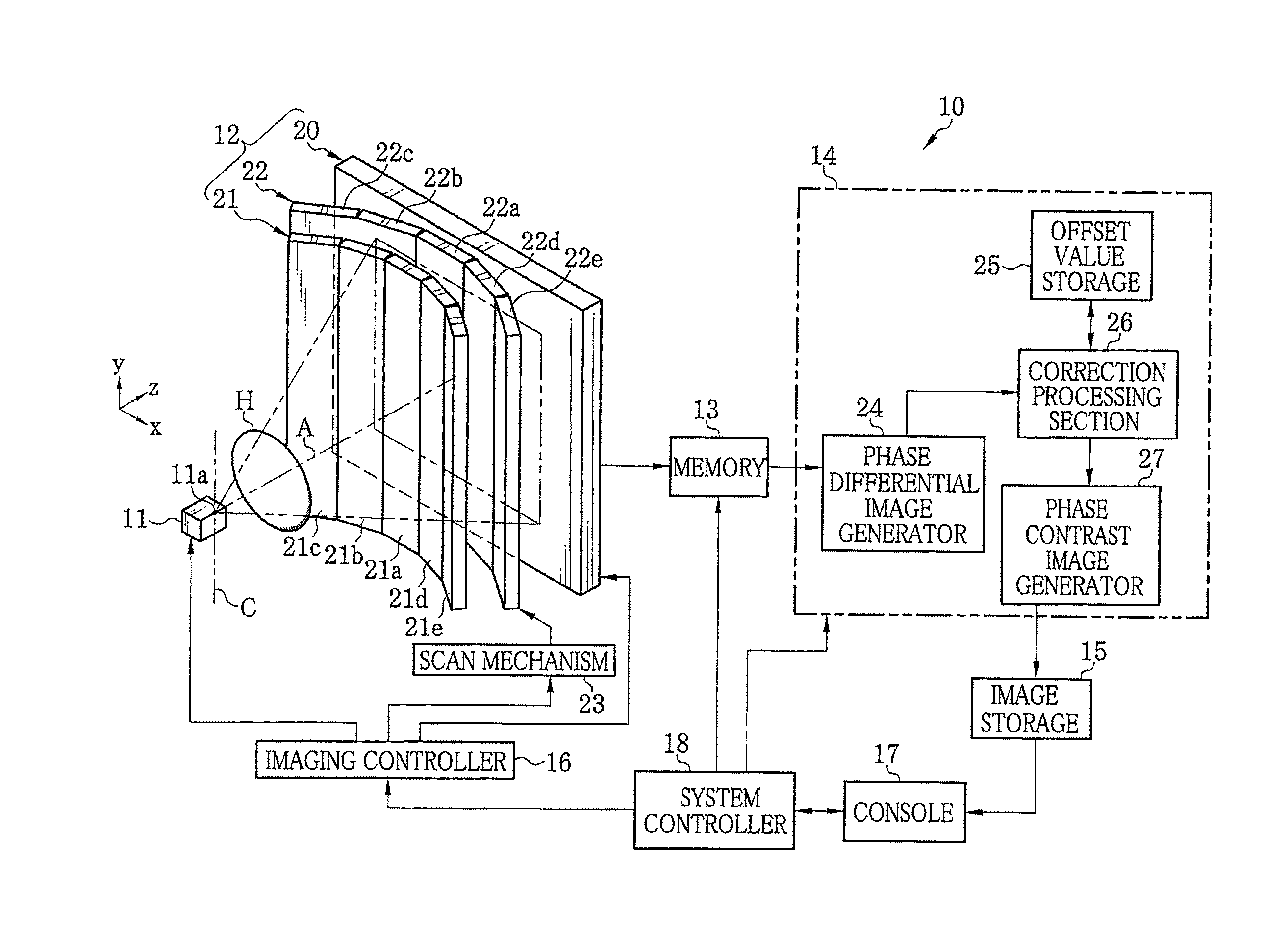
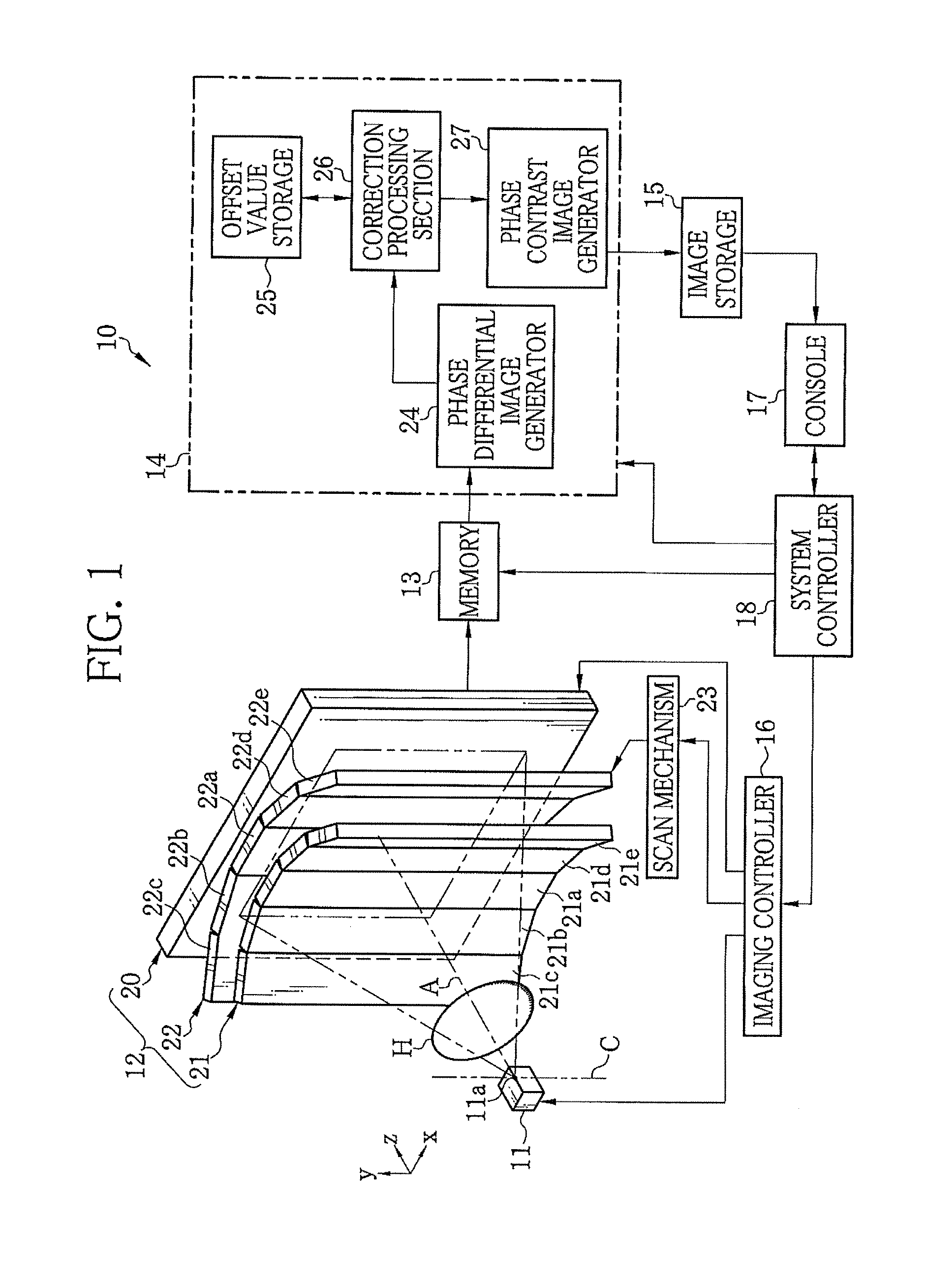
[0032]In FIG. 1, an X-ray imaging system 10 according to a first embodiment of the present invention is composed of an X-ray source 11, an imaging unit 12, a memory 13, an image processor 14, an image storage 15, an imaging controller 16, a console 17, and a system controller 18. The X-ray source 11 irradiates an object H with X-ray. The imaging unit 12 is opposed to the X-ray source 11 and detects the X-ray, emitted from the X-ray source 11 and passed through the object H, to generate image data. The memory 13 stores the image data read from the imaging unit 12. The image processor 14 processes multiple frames of image data stored in the memory 13 to generate a phase contrast image. The image storage 15 stores the phase contrast image generated by the image processor 14. The imaging controller 16 controls the X-ray source 11 and the imaging unit 12. The console 17 is composed of an operating section, a monitor, and the like. The system controller 18 controls the overall operation o...

Example

Second Embodiment

[0093]In the above embodiments, the second absorption grating 22 is provided independently of the FPD 20. With the use of an X-ray detector disclosed in U.S. Pat. No. 7,746,981 corresponding to Japanese Patent Laid-Open Publication No. 2009-133823, the second absorption grating 22 can be eliminated. The X-ray image detector is a direct conversion type X-ray image detector provided with a conversion layer and charge collection electrodes. The conversion layer converts the X-ray into electric charge. The charge collection electrodes collect the converted electric charge. The charge collection electrode in each pixel is composed of linear electrode groups arranged to have mutually different phases. Each linear electrode group is composed of linear electrodes arranged at a predetermined period and electrically connected to each other. The charge collection electrode constitutes the intensity modulator.

[0094]In FIG. 10, an X-ray image detector (FPD) of this embodiment is...


PUM


Abstract

A radiation imaging system includes first and second gratings, a scanning system, a detector, an image generator, a storage, and a correction processing section. The first grating includes first grating modules arranged cylindrically about a virtual line. The virtual line passes through a focal point. The second grating includes second grating modules arranged cylindrically and coaxially about the virtual line with a larger radius. Grating lines of the first and second gratings are parallel with the virtual line. The scanning mechanism scans the second grating orthogonally to the virtual line. The detector is divided into segments corresponding to the second grating modules. The storage stores an offset value, per segment, corresponding to an inclination angle of the second grating module relative to scanning. The correction processing section corrects a phase differential image on a segment-by-segment basis based on the offset value.

Description

FIELD OF THE INVENTION[0001]The present invention relates to a radiation imaging system for capturing an image of an object using radiation such as X-ray and more particularly to a radiation imaging system for performing phase imaging using two gratings arranged between a radiation source and a radiation image detector, and an offset correction method thereof.BACKGROUND OF THE INVENTION[0002]X-ray attenuates while it passes through a substance. The attenuation depends on an atomic number of an element constituting the substance and density and thickness of the substance. A probe for examining the inside of an object using X-ray exploits this X-ray attenuation property. X-ray imaging is commonly used in medical diagnoses and non-destructive inspections.[0003]A common X-ray imaging system captures a radiograph or X-ray transmission image of an object arranged between an X-ray source for emitting X-ray and an X-ray image detector for detecting the X-ray. The X-ray emitted from the X-ra...

Claims


Application Information

Patent Timeline
IPC IPC(8): G01N23/04
CPCG01N23/04A61B6/484G01N2223/33G01N2223/1016G01N23/041
Inventor TADA, TAKUJI
Owner FUJIFILM CORP
Why Eureka
Try Eureka