
Sub-rate sampling in coherent optical receivers

a coherent optical receiver and sub-rate sampling technology, applied in the field of optical communication apparatus, systems and techniques, can solve the problem of limiting the performance penalty of the receiver system to no more than 0.5 db, and achieve the effects of reducing the sampling rate, low gate count, and low power dissipation

Inactive Publication Date: 2011-09-29
OPNEXT SUBSYST
View PDF5 Cites 65 Cited by
  • Summary
  • Abstract
  • Description
  • Claims
  • Application Information

AI Technical Summary

Benefits of technology

[0005]The apparatus and methods described in this document can be implemented to achieve one or more potential benefits. For example, analog-to-digital conversion can be less than two times the rate of the incoming symbols. For instance, the disclosed technology can limit a performance penalty of the receiver system to no more than 0.5 dB down to a sampling rate of 1.25×, even when the CD is as large as 23,000 ps / nm. In addition, the reduced sampling rate enables receiver configurations with low gate count, and consequently, for use in receivers characterized by low power dissipation.

Problems solved by technology

For instance, the disclosed technology can limit a performance penalty of the receiver system to no more than 0.5 dB down to a sampling rate of 1.25×, even when the CD is as large as 23,000 ps / nm.

Method used


Image

  • Sub-rate sampling in coherent optical receivers
  • Sub-rate sampling in coherent optical receivers
  • Sub-rate sampling in coherent optical receivers

Examples


Embodiment Construction

diagram of an example of an analog-to-digital converter.

[0020]FIG. 13A-13B shows aspects related to an example of a symbol rate equalizer.

[0021]FIG. 13C shows a block diagram of an example of a fractionally spaced equalizer.

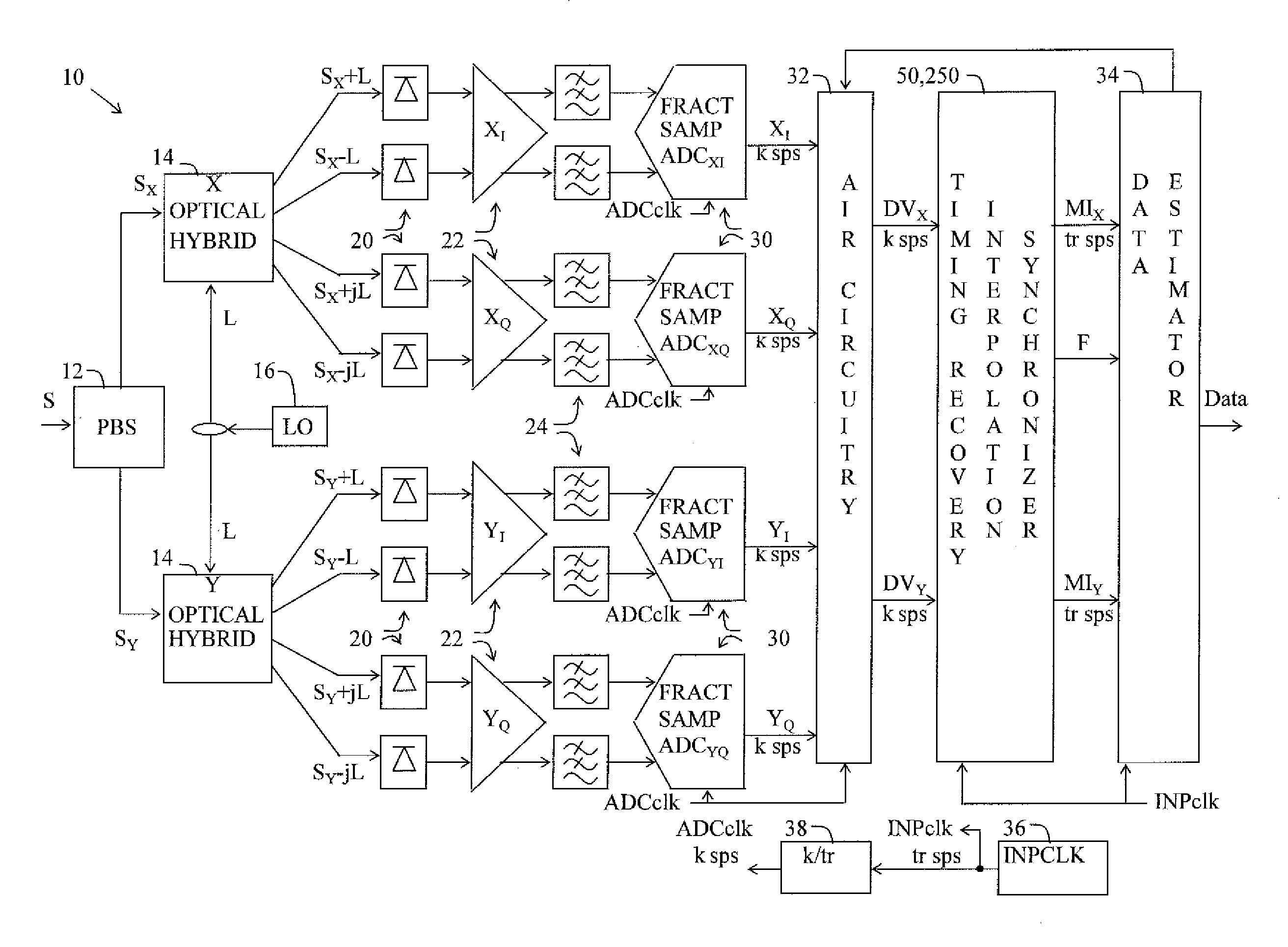
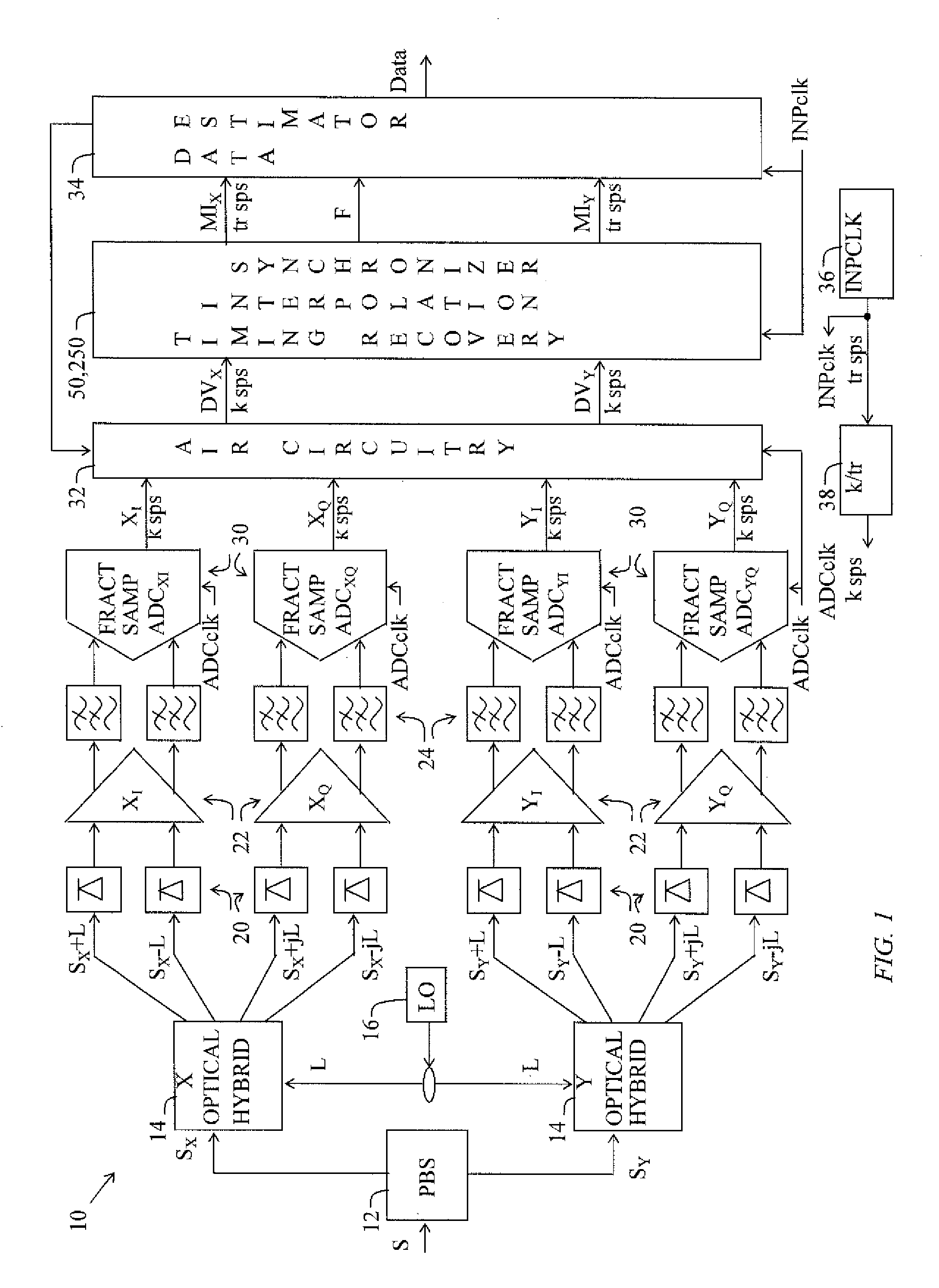
[0022]FIG. 14 shows a block diagram of an example of a receiver system.

[0023]FIG. 15A-15C show block diagrams of an example of a communications system.

[0024]FIG. 16 shows SNR penalty as a function of relative ADC sampling rate and electrical analog bandwidth of an anti-aliasing filtering scheme.

[0025]FIG. 17A shows a block diagram of an example of a communications system.

[0026]FIG. 17B shows a block diagram of another example of a communications system.

[0027]FIG. 18 shows results of experiments performed using the communication system illustrated in FIGS. 15A-15C.

DETAILED DESCRIPTION

[0028]This document describes systems and techniques for mitigating aliasing effects caused by lowering analog-to-digital (ADC) sampling frequency in a modem (receiver system) configu...


PUM


Abstract

Apparatus and methods for optimizing the interplay between the sampling rate of an ADC of a receiver system and a bandwidth of analog anti-aliasing filters are described. The described technology can be used to mitigate aliasing for receiver systems that operate at fractional sampling rates by optimizing a bandwidth of optical and electrical filters included in the receiver systems.

Description

PRIORITY CLAIM AND RELATED APPLICATIONS[0001]This application claims the benefits of the U.S. Provisional Application No. 61 / 317,627 entitled “Optical Communications Based On Optical Receivers Having Fractional Sampling” and filed Mar. 25, 2010, which is incorporated herein by reference in its entirety.TECHNICAL FIELD[0002]This patent document relates to apparatus, systems and techniques for optical communications.BACKGROUND[0003]Polarization-multiplexed quadrature phase shift keying (PM-QPSK) with coherent detection is a leading modulation format for single-carrier 100 Gb / s long-haul transport. Digital signal processing (DSP) in such a communication system can be enabled by analog-to-digital converters (ADC) sampling the signal at high speed. These digital samples are then subsequently processed to compensate for linear impairments like chromatic dispersion (CD) and polarization mode dispersion (PMD). It is commonly expected that the sampling rate of the ADC must be 2 Rs or greater...

Claims


Application Information

Patent Timeline
IPC IPC(8): H04B10/06
CPCH03L7/0807H04B10/60H04B10/611H04B10/614H04B10/6161H04L7/005H04L7/0029H04L27/227H04L2025/03509H04L2027/0069H04L5/04H04B10/65
Inventor WAGNER, ANDREWMALOUIN, CHRISTIANSCHMIDT, THEODORE J.
Owner OPNEXT SUBSYST
Learn More