Photoacoustic imaging apparatus and photoacoustic imaging method
a technology of photoacoustic imaging and imaging apparatus, which is applied in the field of photoacoustic imaging apparatus and photoacoustic imaging method, can solve the problems of difficulty in determining whether the optical absorption coefficient of the subject is higher or lower than that of the surrounding medium
- Summary
- Abstract
- Description
- Claims
- Application Information
AI Technical Summary
Benefits of technology
Problems solved by technology
Method used
Image
Examples
first embodiment
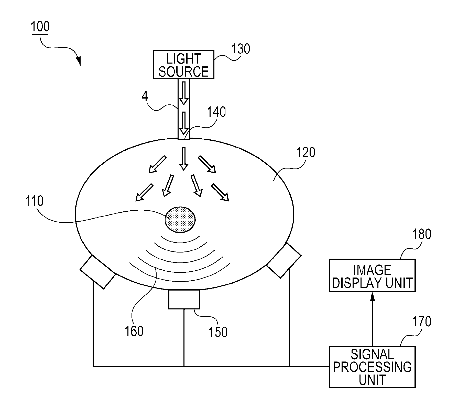
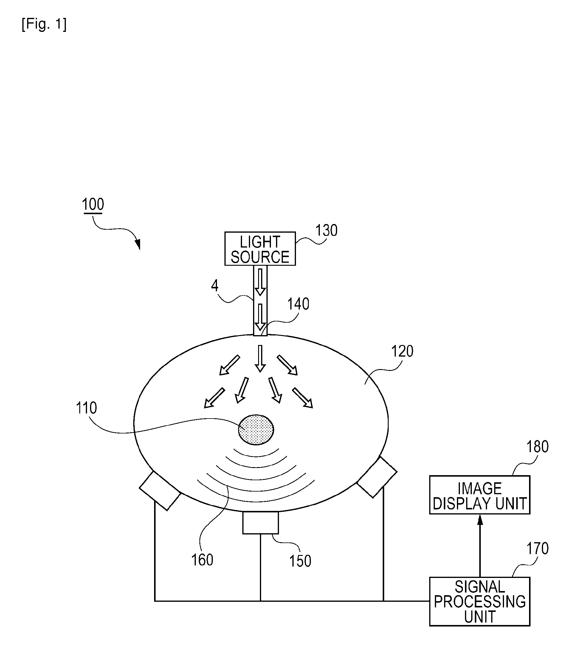
[0047]FIG. 1 illustrates an exemplary configuration of a photoacoustic imaging apparatus 100 according to a first embodiment of the present invention.
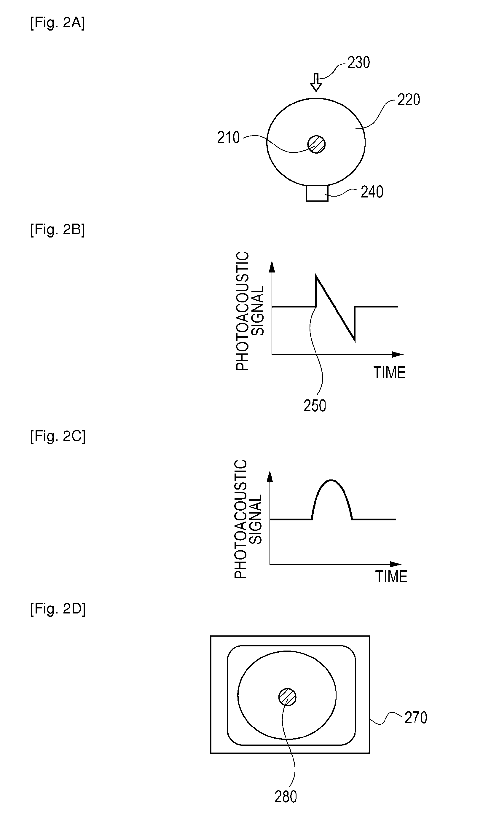
[0048]The photoacoustic imaging apparatus 100 according to this embodiment is capable of imaging optical characteristic values in vivo and a concentration distribution of substances constituting biological tissue obtained from information about those values for the purpose of diagnosing a malignant tumor, a blood vessel disease, and the like, or observing a progress of chemical treatment. Particularly, the photoacoustic imaging apparatus 100 is capable of imaging an optical absorber having an optical absorption coefficient lower than that of a surrounding medium.
[0049]In the photoacoustic imaging apparatus 100 according to this embodiment, light emitted from a light source 130 propagates through an optical fiber 140, so that a living body 120 is irradiated with the light. The living body 120 as a surrounding medium has an optical absor...
second embodiment
[0069]A photoacoustic imaging apparatus according to a second embodiment is different from the photoacoustic imaging apparatus 100 according to the first embodiment in that an image formation process is performed after a normal envelope detection process has been performed. That is, in the first embodiment, image formation is performed after the positive / negative of acoustic pressure data after envelope detection has been inverted. On the other hand, in the second embodiment, image formation is performed without performing such a process. The configuration of the apparatus according to the second embodiment is the same as that of the first embodiment except for signal processing and image reconstruction, and thus the description thereof is omitted.
[0070]FIG. 5 is a flowchart of signal processing and image reconstruction according to the second embodiment.
[0071]First, a focus transducer serving as the detector 150 detects a photoacoustic signal (S510).
[0072]Subsequently, the signal p...
third embodiment
[0079]A photoacoustic imaging apparatus according to a third embodiment is different from the photoacoustic imaging apparatuses according to the first and second embodiments in that image reconstruction is performed by using an algorithm based on delay and sum or an algorithm based on Fourier transform. As a detector according to this embodiment, a detector capable of detecting signals from various regions should be used. Other than the foregoing points, the configuration of the apparatus according to the third embodiment is the same as that according to the first embodiment, and thus the description thereof is omitted.
[0080]FIG. 6 is a flowchart of signal processing and image reconstruction according to the third embodiment.
[0081]First, the detector 150 detects a photoacoustic signal (S610).
[0082]Subsequently, the signal processing unit 170 stores pressure change information of the photoacoustic signal (S620), performs Hilbert transform on data of the photoacoustic signal (S630), a...
PUM
 Abstract
Description
Claims
Application Information
 - R&D
- Intellectual Property
- Life Sciences
- Materials
- Tech Scout
- Unparalleled Data Quality
- Higher Quality Content
- 60% Fewer Hallucinations
Browse by: Latest US Patents, China's latest patents, Technical Efficacy Thesaurus, Application Domain, Technology Topic, Popular Technical Reports.
© 2025 PatSnap. All rights reserved.Legal|Privacy policy|Modern Slavery Act Transparency Statement|Sitemap|About US| Contact US: help@patsnap.com


