Hybrid drive device

a drive device and hybrid technology, applied in the direction of mechanical actuation clutches, propulsion by capacitors, gearing, etc., can solve the problems of rotary electric machines producing heat, rotary electric machines which require precise control, and heat generation of rotary electric machines, so as to reduce the axial dimension of the entire device

Inactive Publication Date: 2011-10-06
AISIN AW CO LTD
View PDF10 Cites 35 Cited by
  • Summary
  • Abstract
  • Description
  • Claims
  • Application Information

AI Technical Summary

Benefits of technology

[0008]Thus, there is desired a hybrid drive device in which a clutch and a rotary electric machine can be individually cooled appropriately, a clutch housing member provided to effectively cool the clutch can be supported appropriately and smoothly, and further the axial dimension of the entire device can be reduced.
[0028]According to the configuration, the shaft-side coupling portion and the hub-side coupling portion can be coupled to each other with the shaft-side coupling portion supporting the hub-side coupling portion in the axial direction from the other side in the axial direction in the notched groove of the shaft-side coupling portion. In this event, the notched groove can be formed relatively easily and precisely by forming the notched groove in the shaft-side coupling portion extending radially outward from the first shaft, which is a shaft member that is generally easy to machine.

Problems solved by technology

When the clutch switches on and off transfer of a drive force, in general, a plurality of friction plates provided in the clutch are caused to slip over each other, and thus produce heat.
When the rotary electric machine outputs torque, meanwhile, the rotary electric machine produces heat due to occurrence of so-called copper loss, iron loss, and so forth.
However, foreign matter such as minute metal pieces may mix into oil sealed in the device, and in the case where such foreign matter adheres to the rotary electric machine, the rotary electric machine which requires precise control may be affected.
However, no solutions to such issues are provided in Japanese Patent Application Publication No. 2005-112351.

Method used


Image

  • Hybrid drive device
  • Hybrid drive device
  • Hybrid drive device

Examples


first embodiment

1. First Embodiment

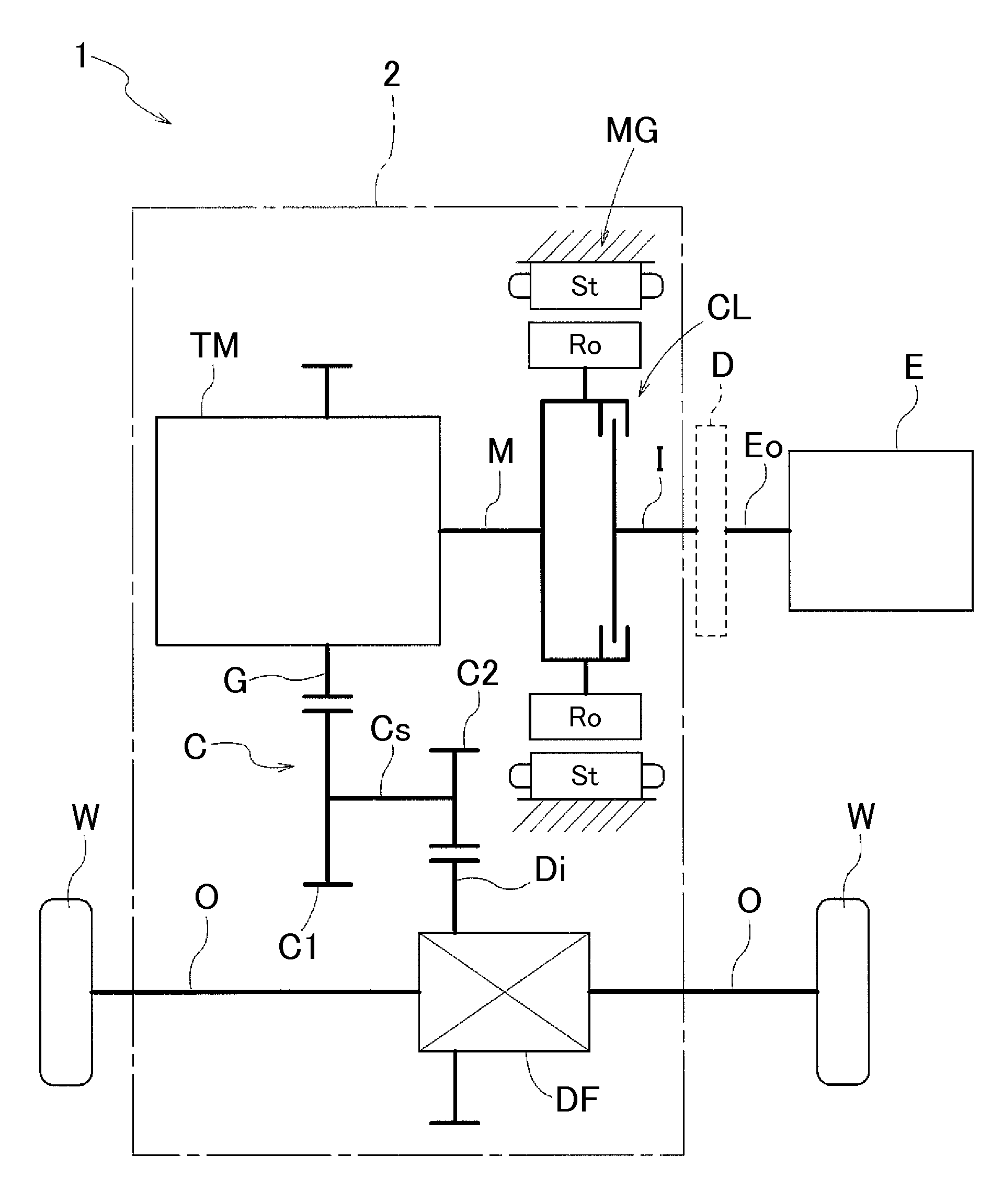
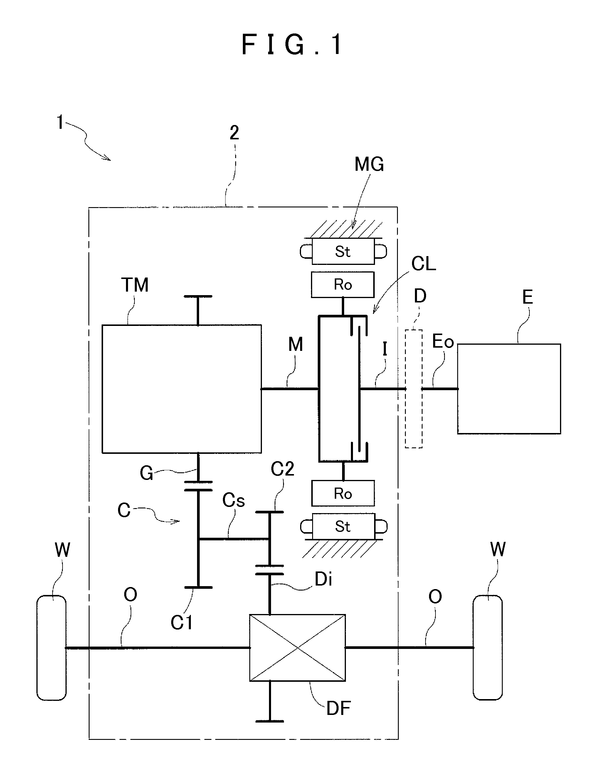
[0036]A first embodiment of the present invention will be described with reference to the drawings. A hybrid drive device 1 is a drive device for a hybrid vehicle that uses one or both of an internal combustion engine E and a rotary electric machine MG as a drive force source for the vehicle. The hybrid drive device 1 is formed as a so-called one-motor parallel type hybrid drive device.

[0037]As shown in FIG. 1, the hybrid drive device 1 according to the embodiment includes an input shaft I drivably coupled to the internal combustion engine E, the rotary electric machine MG, an intermediate shaft M drivably coupled to the rotary electric machine MG and a speed change mechanism TM, a clutch CL provided to switch on and off transfer of a drive force between the input shaft I and the intermediate shaft M, and a case 2 that houses the input shaft I, the intermediate shaft M, the clutch CL, and so forth. The hybrid drive device 1 according to the embodiment configured a...

second embodiment

2. Second Embodiment

[0090]A second embodiment of the present invention will be described with reference to the drawings. The overall configuration of the hybrid drive device 1 according to the embodiment and the configuration of respective sections of the hybrid drive device 1 are basically the same as those in the above first embodiment. In the embodiment, however, the arrangement of the rotatably supporting structure and the sealing structure for the clutch housing CH with respect to the case 2 on the other side in the axial direction with respect to the clutch housing CH is partially different from that in the above first embodiment. Thus, the differences from the above first embodiment will be mainly described in detail below. The same elements as those in the above first embodiment will not be specifically described.

[0091]In the embodiment, as shown in FIG. 4, no stepped portion in the axial direction (the stepped portion 46a in the above first embodiment; see FIG. 3) is formed...


PUM


Abstract

The present invention relates to a hybrid drive device including a first shaft coupled to an internal combustion engine, a rotary electric machine, a second shaft disposed coaxially with the first shaft and coupled to the rotary electric machine and a speed change mechanism, a clutch is provided to switch on and off transfer of a drive force between the first shaft and the second shaft, and a case houses the first shaft, the second shaft, the rotary electric machine, and the clutch. A rotor of the rotary electric machine is fixed to an outer peripheral portion of the clutch housing. A first seal mechanism is disposed in contact with an outer peripheral surface of the large diameter portion of the second axially projecting portion and the inner peripheral surface of the first axially projecting portion, and side by side with the first support mechanism in the axial direction.

Description

INCORPORATION BY REFERENCE[0001]The disclosure of Japanese Patent Application No. 2010-081513 filed on Mar. 31, 2010 including the specification, drawings and abstract is incorporated herein by reference in its entirety.BACKGROUND OF THE INVENTION[0002]The present invention relates to a hybrid drive device including a first shaft drivably coupled to an internal combustion engine, a rotary electric machine, a second shaft disposed coaxially with the first shaft and drivably coupled to the rotary electric machine and a speed change mechanism, a clutch provided to switch on and off transfer of a drive force between the first shaft and the second shaft, and a case that houses the first shaft, the second shaft, the rotary electric machine, and the clutch.DESCRIPTION OF THE RELATED ART[0003]A device disclosed in Japanese Patent Application Publication No. 2005-112351 below, for example, is already known as a hybrid drive device including a first shaft drivably coupled to an internal combu...

Claims


Application Information

Patent Timeline
Patent Type & Authority Applications(United States)
IPC IPC(8): B60K6/38F16H37/06F16D13/38B60L50/16
CPCB60K6/387B60K6/405B60K6/48B60L11/005B60L11/14Y10T74/19051Y02T10/6221Y02T10/7022Y02T10/7077Y02T10/70Y10T74/19014B60L2240/36B60L50/40B60L50/16Y02T10/62Y02T10/7072B60K2006/4825F16D25/123F16D25/0638
Inventor KASUYA, SATORUKATOU, HIROSHIKITOU, MASASHISEKI, YUICHITAKAHASHI, YUSUKE
Owner AISIN AW CO LTD
Why Eureka
Try Eureka