Power transmission device for hybrid vehicle

a technology for power transmission and hybrid vehicles, which is applied in the direction of engine-driven generators, transportation and packaging, and transportation, etc., can solve the problems of increasing limiting the possibility of achieving a reduced size, and the inability to achieve a compact power transmission device, so as to achieve the effect of reducing the size of the motor

Inactive Publication Date: 2011-10-06
HONDA MOTOR CO LTD
View PDF17 Cites 37 Cited by
  • Summary
  • Abstract
  • Description
  • Claims
  • Application Information

AI Technical Summary

Benefits of technology

[0005]In view of the above background, an object of the present invention is to provide a power transmission device for a hybrid vehicle which permits a simplified construction of a speed changing unit that establishes a plurality of gear shift stages and also allows a lightweight, compact construction to be achieved by permitting a reduced size of a motor.

Problems solved by technology

However, the construction adapted to select one of the input shafts of the individual speed changing units and the input shaft of the second speed changing unit and to connect the selected one to the power shaft of the internal combustion engine inevitably involves a complicated construction due to the arrangement of the speed changing units and both clutches, thus limiting the possibility of achieving a reduced size.
This inevitably results in an increased size of the motor, making it impossible to achieve a compact power transmission device.

Method used


Image

  • Power transmission device for hybrid vehicle
  • Power transmission device for hybrid vehicle
  • Power transmission device for hybrid vehicle

Examples


first embodiment

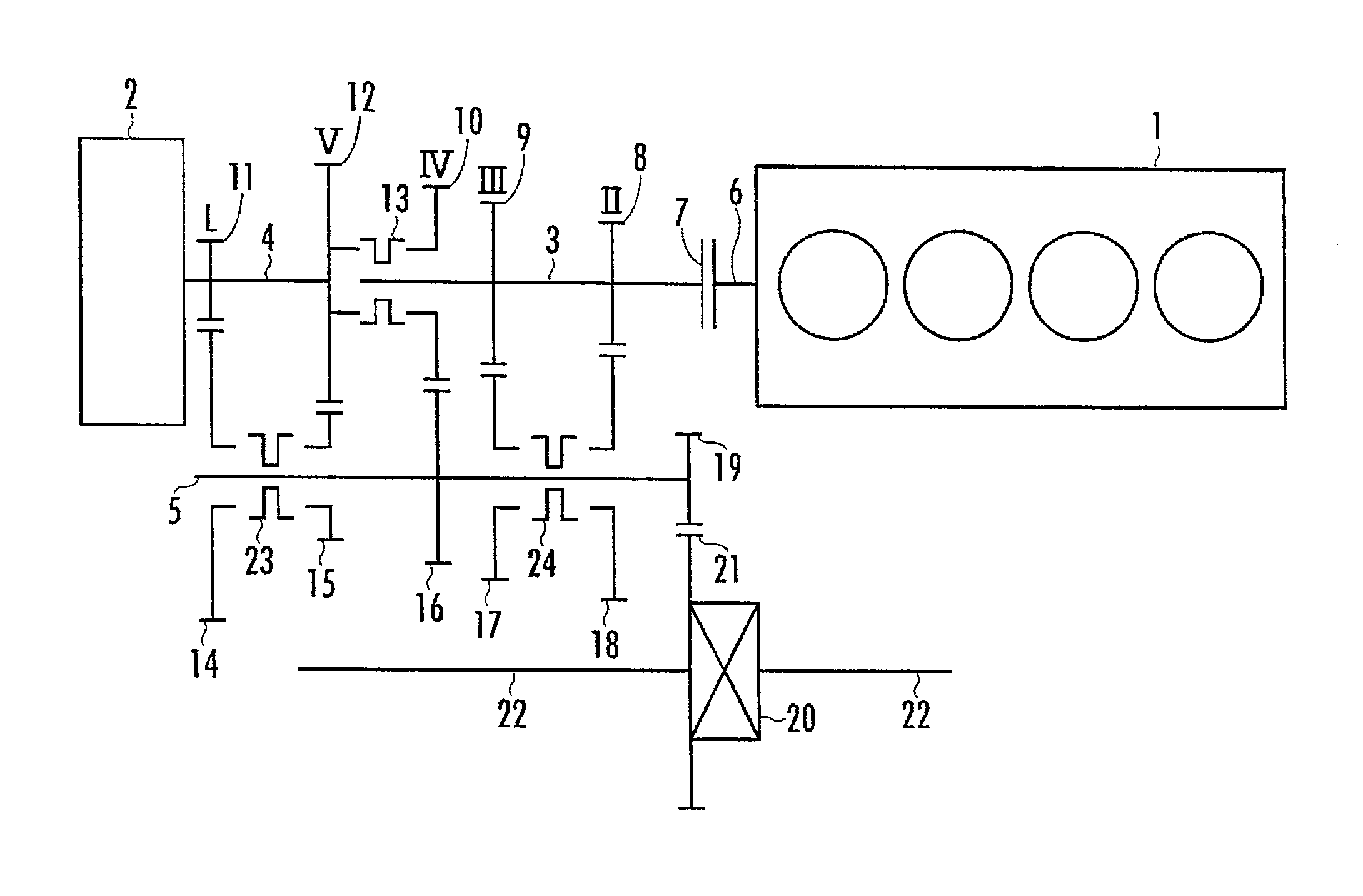
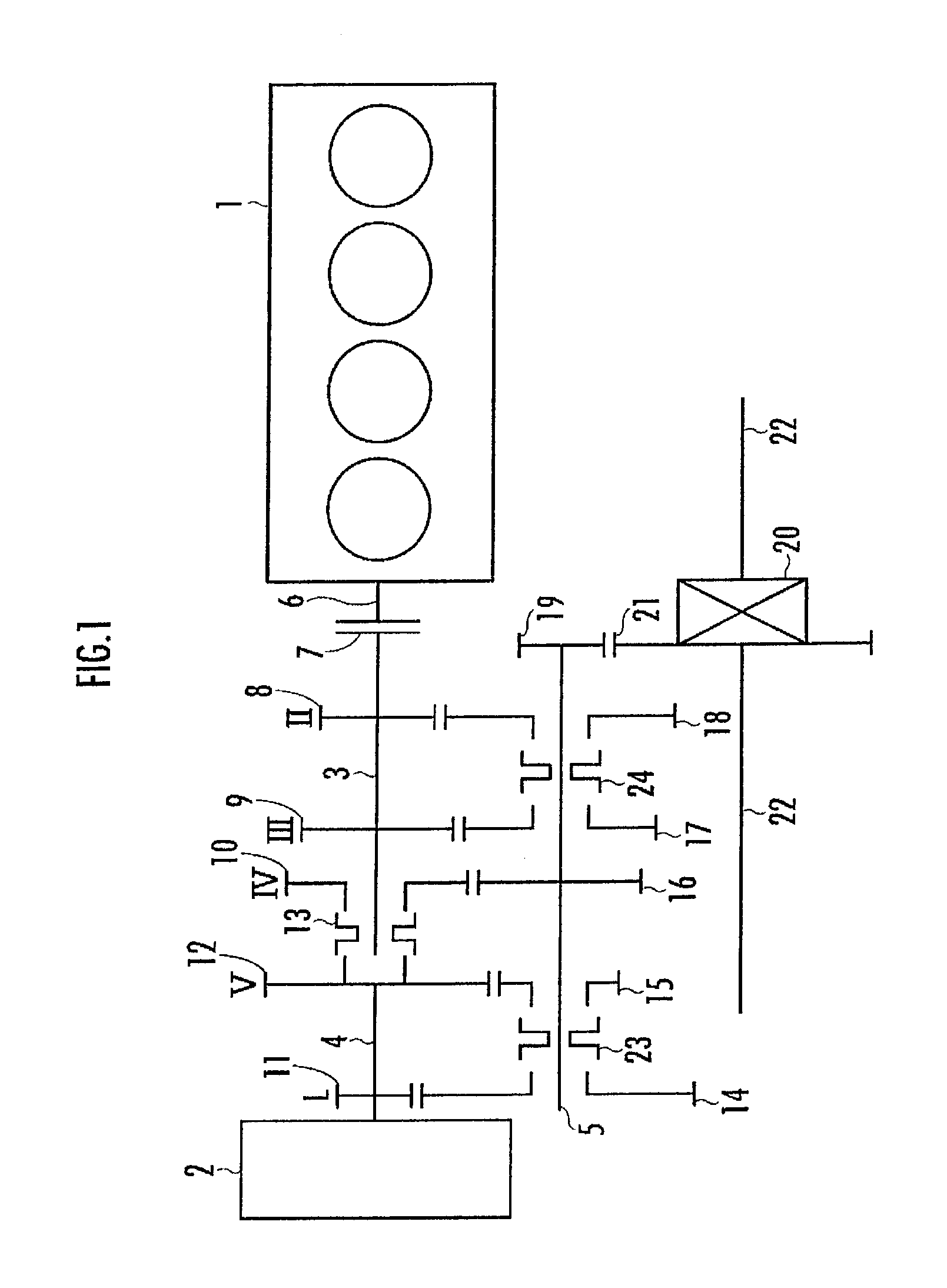
[0015]FIG. 1 schematically illustrates a power transmission device for a hybrid vehicle in the present invention. As illustrated in FIG. 1, a power transmission device according to the present embodiment is provided with an engine 1 (internal combustion engine) and a motor 2 (motor / generator) as the driving sources. The power transmission device is further provided with a first input shaft 3, a second input shaft 4 and an output shaft 5, which are all rotatively mounted. The first input shaft 3 and the second input shaft 4 are disposed coaxially with each other, while the output shaft 5 is disposed in parallel to the first input shaft 3 and the second input shaft 4.

[0016]The first input shaft 3 is extendedly provided, being disposed coaxially with an engine power shaft 6 through which the power rotation from the engine 1 is output, and a friction engagement clutch 7 is provided between the first input shaft 3 and the engine power shaft 6. The engine power shaft 6 and the first input...

fourth embodiment

[0038]Further, in a fourth embodiment illustrated in FIG. 4, each of a first connecting unit 13 and a third connecting unit 24 may be provided with a one-way clutch. More specifically, the first connecting unit 13 may be divided into two portions, one portion being adjacent to a fifth-speed drive gear 12 and the other portion being adjacent to a fourth-speed drive gear 10, and one-way clutches 25a and 25b are interposed between each of the two portions and a first input shaft 3. Similarly, the third connecting unit 24 may be divided into two portions, one portion being adjacent to a second-speed drive gear 8 and the other portion being adjacent to a third-speed drive gear 9, and one-way clutches 26a and 26b are interposed between each of the two portions and the first input shaft 3. This arrangement permits a shortened gear shifting time. More specifically, in the case of, for example, the configuration illustrated in FIG. 1, to shift the speed from the second-speed gear shift stage...

fifth embodiment

[0039]Further, in comparison to the configuration illustrated in FIG. 4, illustrated in FIG. 5, the position of a third-speed drive gear 9 and the position of a fourth-speed drive gear 10 are switched, and one-way clutches 27 and 28 are provided without dividing each of a first connecting unit 13 and a third connecting unit 24. This arrangement makes it possible to simplify the configurations of the first connecting unit 13 and the third connecting unit 24 and to provide the same advantages as those obtained by the configuration illustrated in FIG. 4.


PUM


Abstract

Provided is a lightweight, compact power transmission device for a hybrid vehicle which permits a simplified construction of a speed changing unit that establishes a plurality of gear shift stages and a reduced size of a motor. The power transmission device is provided with a first speed changing unit which has a first input shaft 3 connected to a power shaft 6 of an internal combustion engine 1 and which establishes a plurality of gear shift stages, and a second speed changing unit which has a second input shaft 4 connected to a power shaft of a motor 2 and which establishes a plurality of gear shift stages which is different from that of the first speed changing unit. The power transmission device is provided with a connecting unit 13 which disconnectably connects the first input shaft 3 and the second input shaft 4.

Description

TECHNICAL FIELD[0001]The present invention relates to a power transmission device for a hybrid vehicle which has an internal combustion engine and an electric motor.BACKGROUND ART[0002]Hitherto, as a power transmission device of this type, there has been known a power transmission device that has a first speed changing unit which establishes a plurality of gear shift stages and a second speed changing unit which establishes a plurality of gear shift stages, which is different from that of the first speed changing unit, wherein an input shaft of the first speed changing unit and a power shaft of an internal combustion engine are connected / disconnected by a first clutch, while an input shaft of the second speed changing unit and the power shaft of the internal combustion engine are connected / disconnected by a second clutch, and a power shaft of a motor is connected to the input shaft of one of the speed changing units (refer to, for example, Japanese Patent Application Laid-Open No. 2...

Claims


Application Information

Patent Timeline
Patent Type & Authority Applications(United States)
IPC IPC(8): B60K6/36F16H37/06B60K6/383B60L50/16
CPCB60K6/48Y10T74/19126B60K2006/4816B60K2006/4841B60K2006/541B60W10/02B60W10/06B60W10/08B60W10/113B60W20/00Y02T10/6221Y02T10/6256Y02T10/6286B60K6/36B60K6/40B60K2006/4808B60K2006/4825Y02T10/6252Y02T10/626B60K6/547B60L15/2054B60L2240/486B60L2240/80Y02T10/72B60L50/16Y02T10/62Y02T10/64Y02T10/7072B60K2006/4833B60K6/383B60W20/15Y02T10/70
Inventor SHIBAHATA, YASUJI
Owner HONDA MOTOR CO LTD
Why Eureka
Try Eureka