
Optical tomographic measuring device

a tomographic measuring and optical tomography technology, applied in the direction of optical radiation measurement, luminescent dosimeters, instruments, etc., can solve the problems of long computation time and time for measuring work, and achieve the effect of accurate optical tomographic image and simple structur

Inactive Publication Date: 2011-10-06
FUJIFILM CORP
View PDF0 Cites 12 Cited by
  • Summary
  • Abstract
  • Description
  • Claims
  • Application Information

AI Technical Summary

Benefits of technology

[0013]The present invention was made in view of the above-described circumstances, and an object thereof is to provide an optical tomographic measuring device that, when carrying out reconstruction of a tomographic image that expresses the density distribution of fluorescence within a living body that is an object of measurement, can reconstruct an accurate optical tomographic image by a simple structure.
[0016]Due thereto, the present invention is used in acquiring and reconstructing an optical characteristic distribution in the measurement plane that corresponds to the position of the object of measurement in the body length direction. Therefore, an accurate optical tomographic image can be reconstructed by a simple structure.
[0019]Due thereto, in the present invention, because the position of the measurement plane can be specified on the basis of the movement amount of the moving component, the position of the measurement plane can be grasped accurately from the movement amount, and an optical characteristic distribution corresponding to the measurement position can be acquired.
[0022]As described above, in accordance with the present invention, there is the effect that, when reconstructing a tomographic image expressing the density distribution of fluorescence within a living body that is an object of measurement, an accurate optical tomographic image can be reconstructed by a simple structure.

Problems solved by technology

Carrying out inverse problem computation in two systems by using the respective measurement results requires time for the measuring work, and the computation time also is long.

Method used


Image

  • Optical tomographic measuring device
  • Optical tomographic measuring device
  • Optical tomographic measuring device

Examples


Embodiment Construction

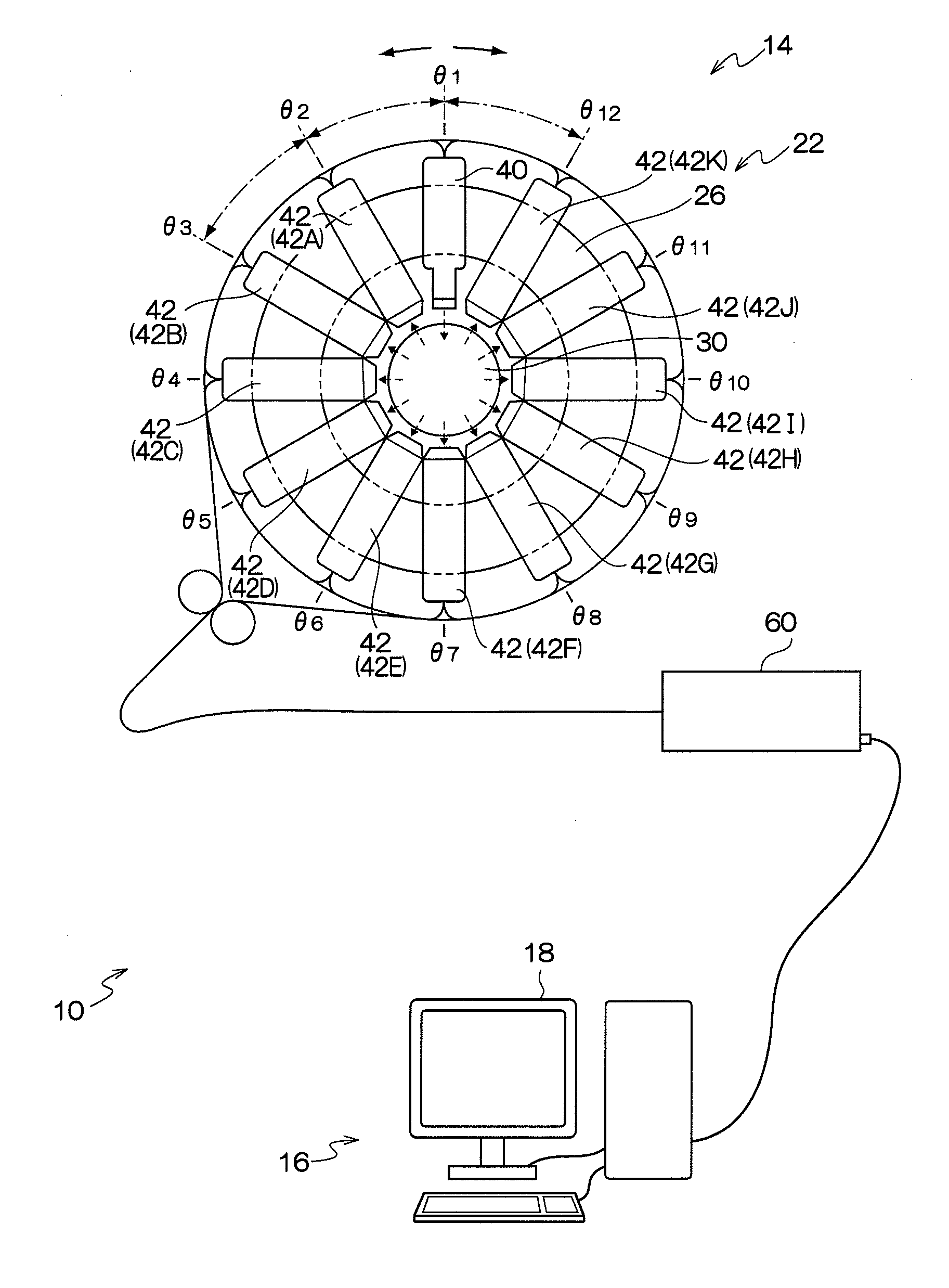
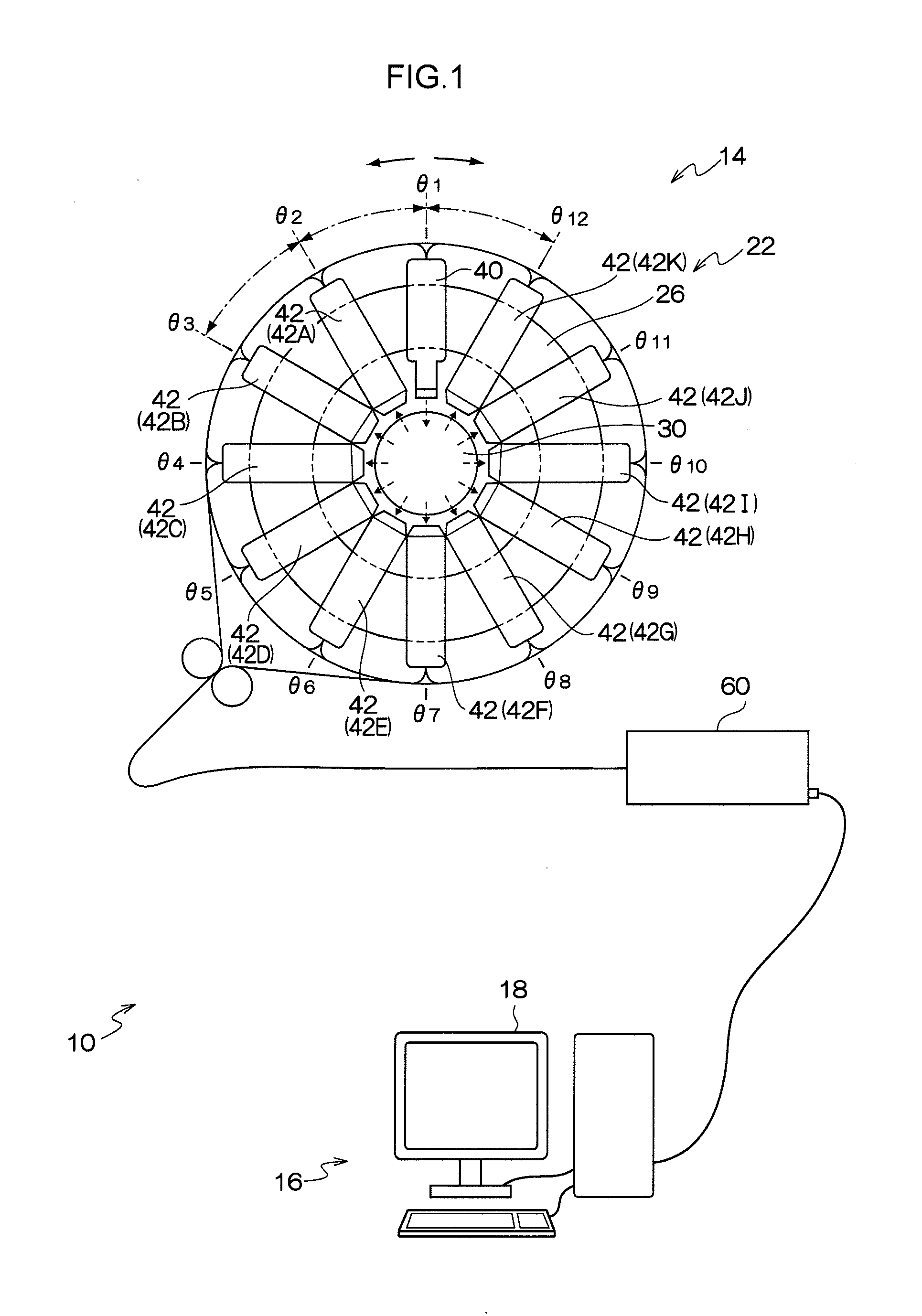
[0037]An exemplary embodiment of the present invention is described hereinafter with reference to the drawings. The schematic structure of an optical tomographic measuring system 10 relating to the present exemplary embodiment is shown in FIG. 1. The optical tomographic measuring system 10 has an optical measuring device 14 and a data processing device 16 that carries out predetermined data processing on measurement data that is obtained at the optical measuring device 14. Note that the optical tomographic measuring, system 10 may be a structure in which the functions of the optical measuring device 14 and the functions of the data processing device 16 are integrated.

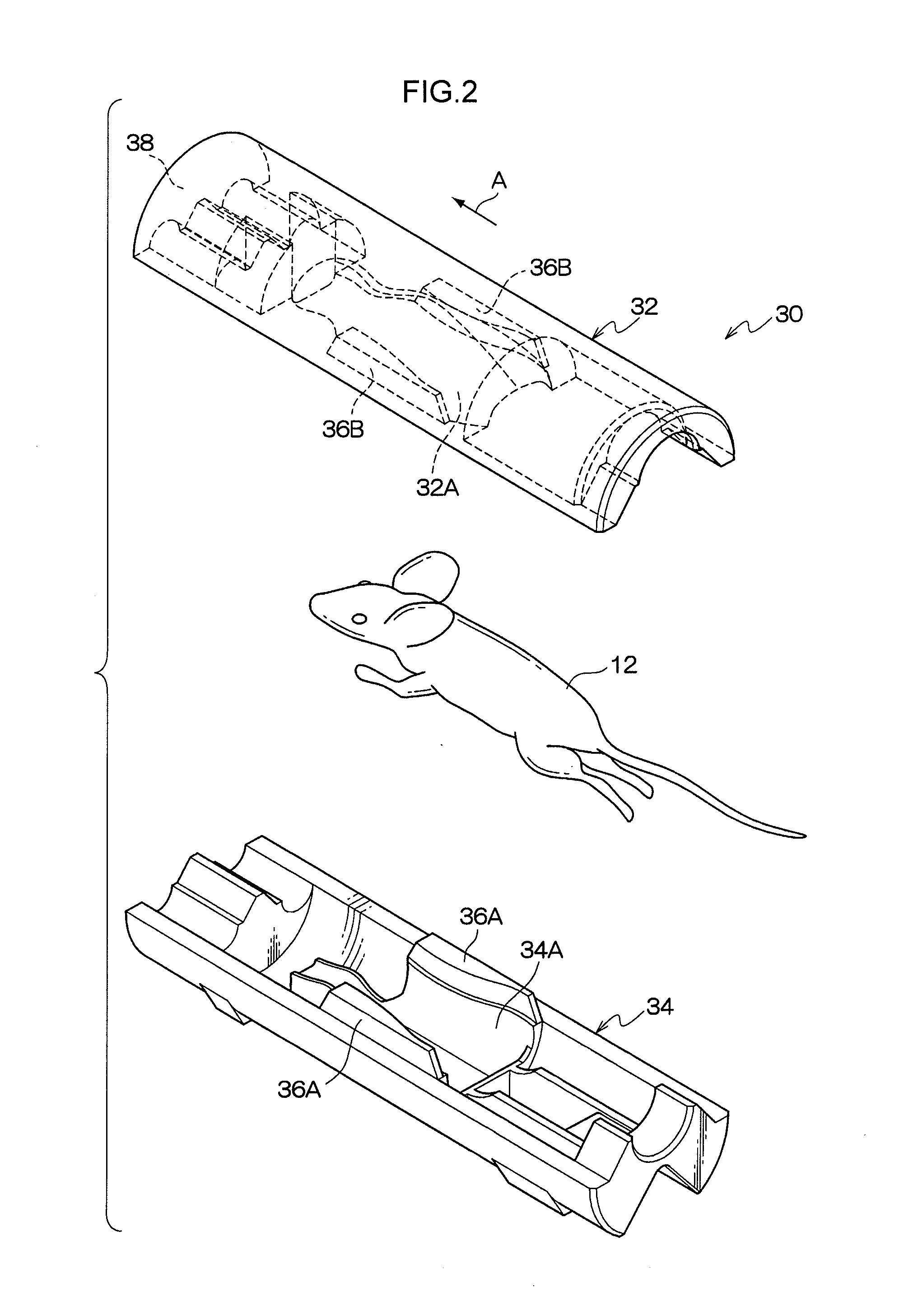
[0038]At the optical tomographic measuring system 10, a living body, such as a nude mouse or the like for example, is the object of measurement. Description is given hereinafter with the object of measurement being a mouse 12 (see FIG. 2). Note that the object of measurement is not limited to the mouse 12, and an arbitr...


PUM

PropertyMeasurementUnit
Lengthaaaaaaaaaa
Fluorescenceaaaaaaaaaa
Density distribution functionaaaaaaaaaa

Abstract

An optical tomographic measuring device that includes: an illuminating component, a plurality of light-receiving components, a storage component, a specifying component, an acquiring component, and a constructing component is provided. The specifying component specifies a position of the measurement plane in the body length direction. The acquiring component acquires, from the storage component, an optical characteristic distribution that corresponds to the position specified by the specifying component. The constructing component constructs a density distribution of fluorescence in the measurement plane, on the basis of intensities of the fluorescence received at the respective light-receiving components and the optical characteristic distribution acquired by the acquiring component.

Description

CROSS-REFERENCE TO RELATED APPLICATION[0001]This application claims priority under 35 USC 119 from Japanese Patent Application No. 2010-082238 filed on Mar. 31, 2010, the disclosure of which is incorporated by reference herein.BACKGROUND OF THE INVENTION[0002]1. Field of the Invention[0003]The present invention relates to an optical tomographic measuring device that measures fluorescence, that is emitted from a living body that is an object of measurement in accordance with excitation light, and reconstructs an optical tomographic image.[0004]2. Description of the Related Art[0005]It is known that tissue of a living body is light-transmissive with respect to light of predetermined wavelengths, such as near infrared rays and the like. From this, observation of the interior of a living body by using light (optical tomography: optical CT) is proposed in Japanese Patent Application Laid-Open (JP-A) Nos. 11-173976, 11-337476, and the like.[0006]Optical CT is a technique that obtains the ...

Claims


Application Information

Patent Timeline
IPC IPC(8): G01J1/58
CPCA61B5/0071G01N21/6456G01N21/4795A61B5/0073
Inventor YAMAMOTO, HIROAKI
Owner FUJIFILM CORP
Learn More