Cogged belt for conveying articles and/or for power transmission, and a method and an apparatus for realising the cogged belt

a cogged belt and power transmission technology, applied in the field of synchronised conveying and power transmission, can solve the problems of low mechanical resistance and high cost, and limit the application range of cogged belts, and achieve the effects of greater transmittable power, greater flexibility, and greater resistance to traction

Active Publication Date: 2011-10-06
VISION TECH SRL
View PDF1 Cites 5 Cited by
  • Summary
  • Abstract
  • Description
  • Claims
  • Application Information

AI Technical Summary

Benefits of technology

The advantage of the present invention consists in having defined a belt which is provided with a cogged profile (also referred-to in the following as a cogged belt) for synchronised transport applications of articles and / or power transmissions, which fully satisfies the set aims.
With respect to convention flat belts, or belts provided with one or more longitudinal guides, the cogged belt of the invention exhibits: advantageously a greater resistance to traction and thus a greater transmittable power thanks to the presence of the cogged covering which substantially entirely covers a side of the prefabricated belt; and a flexibility and inextensibility which are almost unchanged. With respect to thermoplastic belts in which steel longitudinal reinforcement cores are sunk, the cogged belt of the invention exhibits: advantageously a greater flexibility, such as to enable winding about small-diameter pulleys; on the other hand, it has a smaller resistance to traction and a greater extensibility.
The cogged belt thus obtained advantageously exhibits technical-functional characteristics which are distinct with respect to belts of known type; the limited cost of realisation as well as the optimal flexibility and mechanical resistance make this new type of product, object of the present invention, usable in a great number of industrial applications, for example those where the cogged belt is destined to be wound on smaller-diameter resources.
Obviously a whole series of correlated technical-functional advantages follow on from the possible reduction of diameters of the pulleys on which the cogged belt is destined to wind, such as a reduction in weight, sizes, and thus also costs of the corresponding conveyor organ on which the cogged belt winds.
A further advantage of the present invention consists in having defined a method and an apparatus for realising the above-described cogged belt for the synchronised transport of articles and / or for the transmission of power, in accordance with the predetermined aims.

Problems solved by technology

The prior art comprises cogged belts manufactured in thermoplastic material in which reinforcing metal cores are sunk, arranged in a longitudinal direction and constituted by a plurality of cords or flanked filaments; the belts have high resistance to traction and are thus suitable for power transmission and synchronised transport of articles; in their disfavour, they are expensive and rigid.
These belts exhibit a greater flexibility inasmuch as they are not provided with reinforcement cores, so that they can wind on pulleys of smaller diameter, but their low mechanical resistance limits their range of application.

Method used


Image

  • Cogged belt for conveying articles and/or for power transmission, and a method and an apparatus for realising the cogged belt
  • Cogged belt for conveying articles and/or for power transmission, and a method and an apparatus for realising the cogged belt
  • Cogged belt for conveying articles and/or for power transmission, and a method and an apparatus for realising the cogged belt

Examples


Embodiment Construction

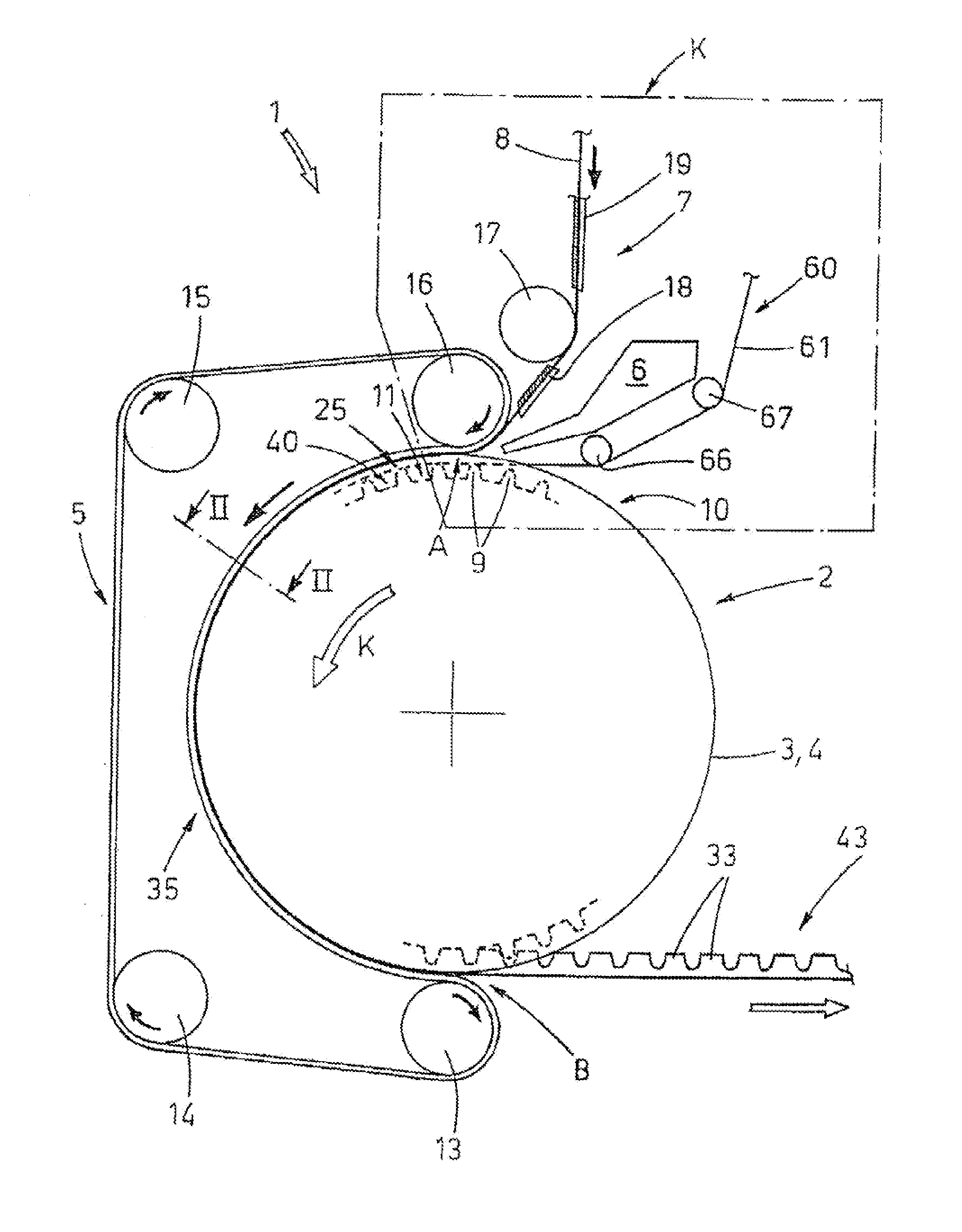
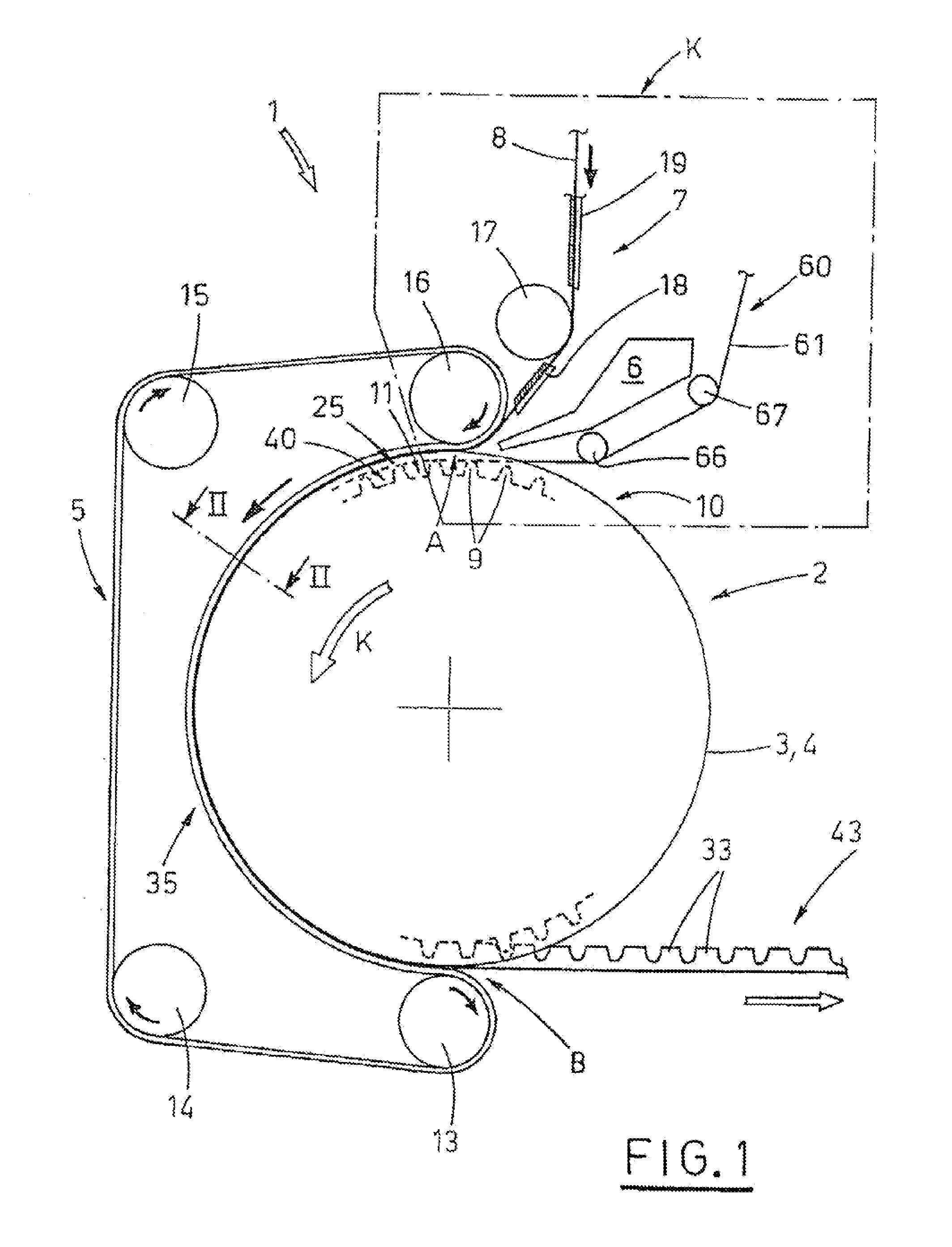
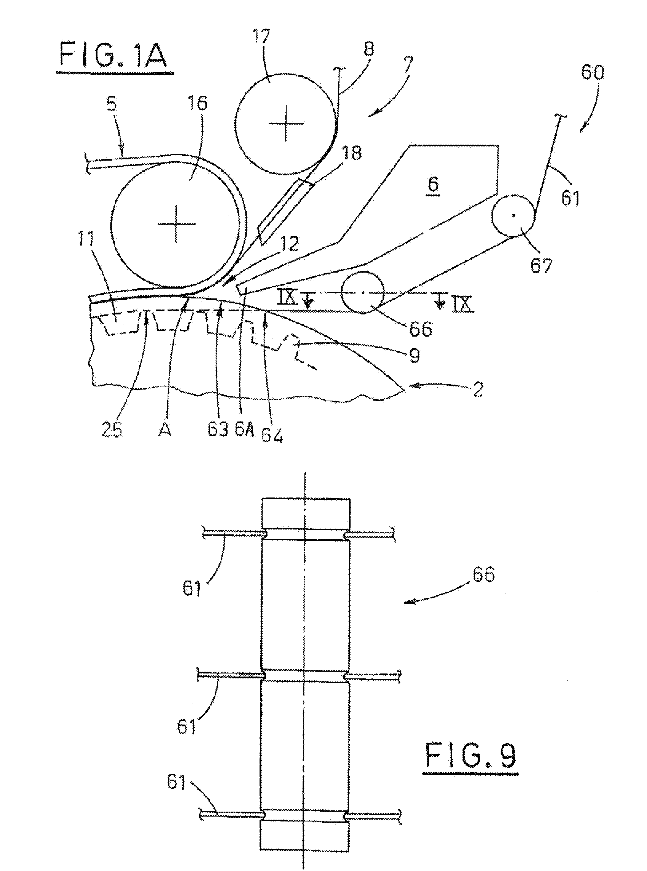
With reference to FIGS. 1, 1A, 2A-2E, 3-6, 8-10, 1 denotes in its entirety the apparatus of the invention for realising, for example continuously, a cogged belt, also an object of the invention, which apparatus 1 comprises a cogged pulley 2 peripherally forming a cogged profile 40, a contrast belt 5, a device 6 for supplying a molten thermoplastic or heat-hardening material, a first station 7 for supplying a prefabricated belt 8 and a second station 60 for supplying a plurality of reinforcing cores 61 that develop longitudinally, and are for example cord-shaped.

The cogged pulley 2 is drawn continuously in rotation by actuator organs, not illustrated, and is provided with two lateral containment edges 3, 4 which are opposite one another and removably fixed to the respective heads, for identifying a seating or circular mould 10 for receiving the molten thermoplastic or heat-hardening material. The lateral edges 3, 4 can project with respect to the extract contact profiles 25 of the co...


PUM

PropertyMeasurementUnit
velocityaaaaaaaaaa
thicknessaaaaaaaaaa
heightaaaaaaaaaa

Abstract

The invention relates to a cogged belt for conveying articles and/or for power transmission, and a method and an apparatus for realisation thereof. The cogged belt (30, 50) comprises: a prefabricated belt (8) comprising a textile or a meshed net; and a covering (26) made of a thermoplastic or heat-hardening material fixed in a single body by fusion to the prefabricated belt (8) and substantially entirely covering a side of the prefabricated belt (8), the covering (26) forming a cogged profile (43). The cogged belt (30, 50) can further comprise at least a cord-shaped reinforcing core (61) at least partially incorporated in the covering (26). The method includes use of a mould (10) which is: mobile, exhibits a longitudinal development and comprises a succession of spaces (11, 11A, 11B) for containment of molten thermoplastic or heat-hardening material, the method comprising stages of: supplying a prefabricated belt (8) which faces the spaces (11, 11A, 11B) and advances at a same velocity as the mobile mould (10), and supplies molten thermoplastic or heat-hardening material into the spaces (11, 11A, 11B) in order to enable formation of a single body (30, 50). An additional stage of the method further includes supplying at least a reinforcing core (61) to be incorporated in the single body (30, 50). The apparatus comprises: a cogged pulley (2) activated by actuator organs; two lateral sides (3, 4) fixed to heads of the pulley (2); a contrast belt (5) facing a circular sector of the pulley (2); a supply device (6) of molten thermoplastic or heat-hardening material; a first station (7) for supplying a prefabricated belt (8), and an additional second station (60) for supplying at least a reinforcing core (61).

Description

TECHNICAL FIELDThe invention relates to the technical sector of synchronised conveying and power transmission. In more detail, the invention relates to a belt provided with a cogged profile for transport of articles and / or power transmission, to a method for realising the belt and an apparatus for actuating the method.BACKGROUND ARTThe prior art comprises cogged belts manufactured in thermoplastic material in which reinforcing metal cores are sunk, arranged in a longitudinal direction and constituted by a plurality of cords or flanked filaments; the belts have high resistance to traction and are thus suitable for power transmission and synchronised transport of articles; in their disfavour, they are expensive and rigid.Where transport of articles does not require high power mechanisms, for example in some applications in the food industry, homogeneous belts are used (for example made entirely of a thermoplastic material) which are flat, i.e. they have a constant thickness along the ...

Claims


Application Information

Patent Timeline
Patent Type & Authority Applications(United States)
IPC IPC(8): B29C45/14B29C48/05B29C48/15
CPCB29C43/28B29C47/0014B29C47/02F16G5/20F16G1/10F16G1/28B29D29/106B29C48/05B29C48/15
Inventor RUBINO, ATTILIOVINCENZI, MAURIZIO
Owner VISION TECH SRL
Why Eureka
Try Eureka