
Ultrasonic system controls, tool recognition means and feedback methods

Active Publication Date: 2011-10-06
RN HLDG LLC
View PDF4 Cites 12 Cited by
  • Summary
  • Abstract
  • Description
  • Claims
  • Application Information

AI Technical Summary

Benefits of technology

[0015]In accordance with one embodiment of the present disclosure, a configuration of three coils, wherein the winding direction of the two distal coils are in the same direction, and a center coil that is wound in the opposite direction from the distal coils. In a preferred configuration, the sum of the windings of the two distal coils equals the number of windings of the center coil. The spacing between the two distal coils relative to the center coil may be symmetrical or asymmetrical. In some cases a small number of additional turns may be added to the distal coils to compensate for the effects of a non-homogeneous magnetic field as the position of the distal coils approach the ends of the drive coil. Another effect that results in inducing voltage into the feedback coils is the changing permeability of the vibrating transducer. A relatively symmetric dynamic stress pattern exists along the length of the transducer with the maximum effect located in the nodal region. This configuration minimizes the effects of transformer coupling between the drive and feedback coils.
[0016]The effect of the pick-up configurations above are further enhanced by addition of a gap in the drive windings. The two sections of the winding are continuous and wound in the same direction including at least one gap at a distal position of the coil. Removing a number of turns in the drive winding in this manner produces a field correction that acts to depress the induced transformer voltages in the feedback coils.
[0017]Another embodiment comprises an asymmetrical two coil configuration with the coils wound in opposite directions. In one configuration, the coils are on opposite sides of the transducers nodal region. The spacing between the coils is determined in part by the length of the transducer and the centerline of the spacing between the coils can be positioned about the nodal region to increase the motional feedback effect. The larger coil can be placed on either side of the nodal region with the preferred position being the one producing the greatest induced motional feedback voltage. This configuration also provides a minimization of the transformer coupling by means of the opposite sense of the windings and the asymmetry of the windings. The feedback signal is generated at least in part by the summation of the induced motional or velocity signals in the feedback coils. The asymmetry of the coils also enhances the motional feedback signal based on the non-homogeneity of the drive field.
[0018]An aspect of this disclosure includes determining the impedance or inductance of a transducer placed in the handpiece. In one embodiment, a bridge circuit is configured to have one leg connected to the drive coil such that it has minimum affect on the operation of the handpiece, drive system or feedback. A suitable stable oscillator is placed across the bridge and an ancillary circuit is connected in quadrature to the oscillator. The output of the bridge is balanced or nulled with a standard tool in place. The nulling operation can be done once during alignment of the circuit, e.g., during testing, at predetermined intervals during normal operation, upon application of power to the drive circuit, or whenever the drive circuit is not activated depending on the application. The null value can then be stored or otherwise processed so that its value can be used as a comparison value when another transducer or tool is placed in the handpiece. The circuit parameters can also be adapted to allow nulling of the circuit when no tool is in the handpiece. In this way, the detection circuit can provide a means to limit power to the handpiece when no transducer is present.
[0020]Current ultrasonic systems have inherent limitations in their ability to capture and lock onto transducers due to manufacturing tolerances of transducer inductance. A transducer outside a specific range of inductance often results in the failure of the electronics to operate the tool, which is in part due to phase shifts outside the normal operating limits of the system. The proposed disclosure has the ability to detect the transducer inductance and apply a correction or change to the oscillator circuit's operational parameters, which allows the system to function normally.

Problems solved by technology

Currently produced ultrasonic systems that use some form of feedback to control the drive frequency are limited by a multitude of compromises.
This poses several problems.
Inherent limitations associated with these prior art systems are that these inputs are often ambiguous due to the effects of manufacturing variations in the tools and operational variations during tool loading.
Current ultrasonic systems have inherent limitations in their ability to capture and lock onto transducers due to manufacturing tolerances of transducer inductance.
A transducer outside a specific range of inductance often results in the failure of the electronics to operate the tool, which is in part due to phase shifts outside the normal operating limits of the system.
A common cause for the transducer to lose inductance is due to work hardening the magnetostrictive material.
For example, dropping a transducer a height of 4 feet can result in a 3% loss of initial inductance.
Even slight deformation of the transducer due to handling and re-straightening the transducer can result in a 10% to 15% loss in inductance.

Method used


Image

  • Ultrasonic system controls, tool recognition means and feedback methods
  • Ultrasonic system controls, tool recognition means and feedback methods
  • Ultrasonic system controls, tool recognition means and feedback methods

Examples


Embodiment Construction

[0027]Particular embodiments of the present disclosure are described hereinbelow with reference to the accompanying drawings. In the following description, well know functions or constructions are not described in detail to avoid obscuring the present disclosure in unnecessary detail.

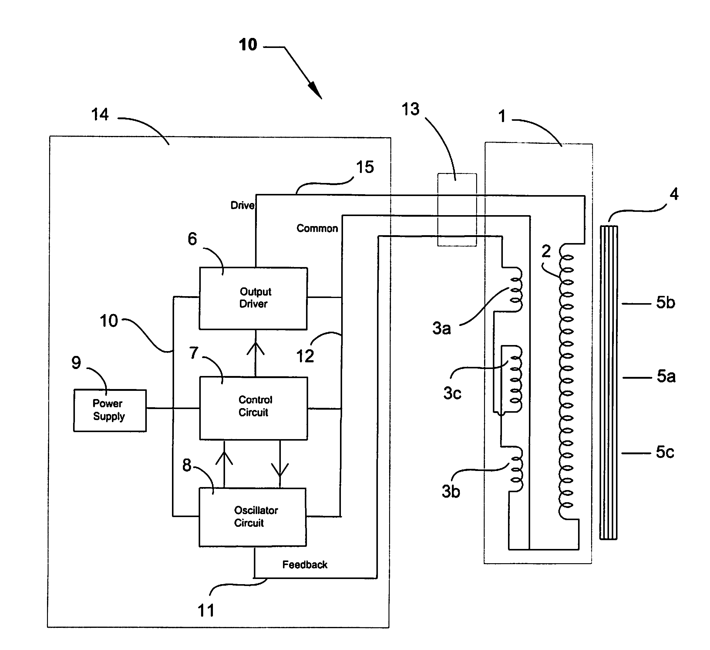
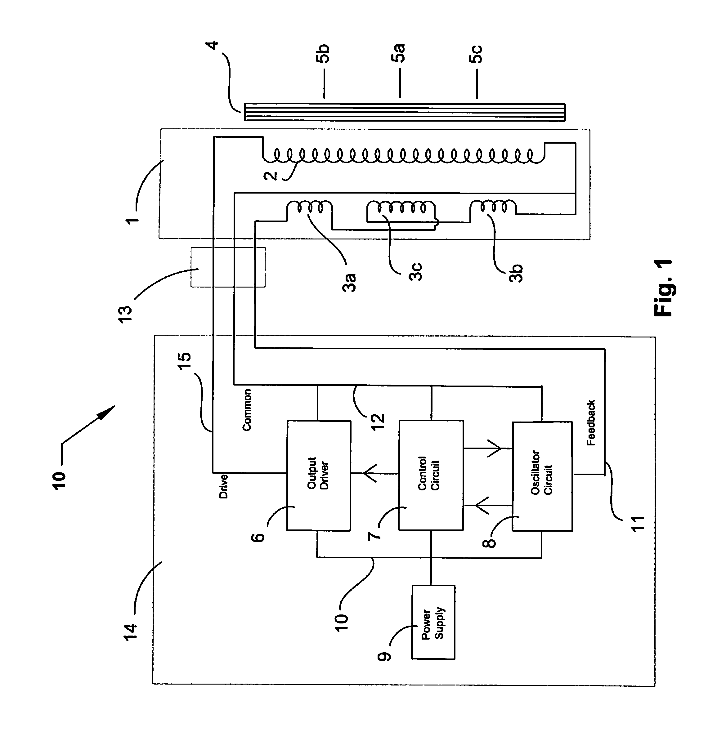
[0028]Turning now to FIG. 1, disclosed is a dental scaler system 10 including a dental scaler device 14, and a handpiece 1 that is operatively coupled to the dental scaler device 14 via a cable 13. The dental scaler device 14 includes a power supply 9, which may be either internal or external to the dental scaler device 14, an oscillator circuit 8, a control circuit 7, and an output driver 6. The power supply 9 provides one or more voltages to the scaler device 14. The one or more voltages provide input to the scaler device 14 (e.g., indicator lights) and its oscillator circuit 8, control circuit 7, and output driver 6, which in combination convert the DC voltage into high frequency signals for driving ...


PUM


Abstract

An ultrasonic electro-mechanical resonant system and instrument that provides improvements in the design and implementation of a feedback system. The disclosed configuration and orientation of coils enhance the motional or velocity feedback signals while minimizing the effects of transformer coupling. A two coil and a three coil approach is disclosed that takes advantage of non-homogeneous magnetic fields. An asymmetrical arrangement enables velocity signals to be coupled into the coils without requiring additional signal conditioning or capacitive elements.

Description

[0001]This application claims the benefit of priority to U.S. Provisional Application Ser. No. 61 / 319,922 entitled “ULTRASONIC SYSTEM CONTROLS, TOOL RECOGNITION MEANS AND FEEDBACK METHODS”, filed Apr. 1, 2010 by Richard H. Paschke, the entirety of which is incorporated by reference herein for all purposes.BACKGROUND[0002]1. Technical Field[0003]The present disclosure relates to ultrasonic electro-mechanical resonant systems. More specifically, the present disclosure relates to improvements in the design and implementation of a feedback system employing the configuration and orientation of coils that enhance the effects of motional or velocity feedback signals and minimize the effects of transformer coupling.[0004]Additionally, the present disclosure relates to a detection system to determine the impedance or inductance of a tool placed in an ultrasonic handpiece. This system includes the ability to differentiate or select tool characteristics prior to and after activation.[0005]2. B...

Claims


Application Information

Patent Timeline
IPC IPC(8): H02K7/14G01R27/28H02N2/06
CPCA61C17/20B06B1/08B06B1/0253
Inventor PASCHKE, RICHARD H.
Owner RN HLDG LLC
Learn More