System and Method for Determining and Predicting IOL Power in Situ

a technology of iol power and system, applied in the field of system and method for determining and predicting iol power in situ, can solve problems such as difficult to perform, and achieve the effect of preventing, treating and/or ameliorating diseases

Inactive Publication Date: 2011-10-06
IOL INNOVATIONS
View PDF0 Cites 35 Cited by
  • Summary
  • Abstract
  • Description
  • Claims
  • Application Information

AI Technical Summary

Benefits of technology

[0029]According to the system and method in this invention, the physical measurements of the human eye, including the measurement of the axial length and the physical position of the IOL, can be correctly interpreted and analyzed by ray tracing techniques to accurately reflect the ocular imagery and thereby be used to calculate the optical properties of the IOL.
[0037]Thus, an object of the present invention is a system which may be used for the prevention, treatment and / or amelioration of diseases and / or disorders which are related to the lens and which may benefit from IOL surgery by predicting the optical properties of a specific IOL in a specific eye, thereby controlling the outcome of refractive IOL surgery.
[0055]2) a realistic model is provided for the optics of the eye with an accurate and correct interpretation of the measured data.
[0075]It should be stressed that similar results and accuracy for calculating the IOL power in situ has not been published before. The present method of accurately interpreting the clinical data from eye measurements, building a realistic non-corrected model of the eye and performing ray tracing analysis based in this model leads to an previously unknown accuracy in determining the IOL power in situ. As will be shown in example 3 the present method leads to an accuracy of 0.66 D in determining the IOL power in situ for a large range of labelled IOL powers. This is a clear improvement compared to previous methods, such as the “thick lens” method.

Problems solved by technology

Although such methods have proven highly accurate they are not easy to perform as they require special equipment not within the normal clinical techniques.

Method used


Image

  • System and Method for Determining and Predicting IOL Power in Situ
  • System and Method for Determining and Predicting IOL Power in Situ
  • System and Method for Determining and Predicting IOL Power in Situ

Examples


example 1

Ray Tracing Analysis of Gullstrand Eye

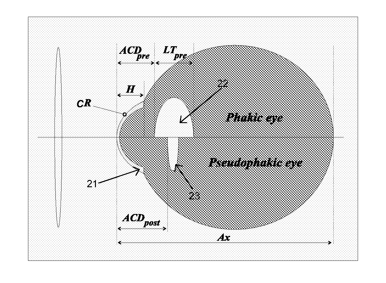
[0200]The exact schematic eye of Gullstrand (Gullstrand, 1909, Gullstrand, 1924) was used as an example of the ray tracing analysis. For many years the exact schematic eye of Gullstrand has been used to simulate the optical properties of the human eye. Apart from the object plane and the image plane the structure of the schematic eye is a 6 surface model as shown in Table 1:

TABLE 1Surfaces of the exact schematic eye of Gullstrand.SurfaceNamex-PositionRadiusConicindex0Object−3010000011Cornea front07.701.382Cornea back0.56.801.343Lens front3.61001.394Nucleus front4.157.9101.415Nucleus back6.57−5.7601.396Lens back7.2−601.347Retina (image)24−1300Each surface is given number from left to right, a name, an axis location (x-Position), a radius of curvature (positive means anterior convex and negative means anterior concave), a conic coefficient (zero for this eye model) and a refractive index.

[0201]In the Gullstrand eye the axial length of the eye is a...

example 2

Ray Tracing Analysis of Eye with IOL Implant

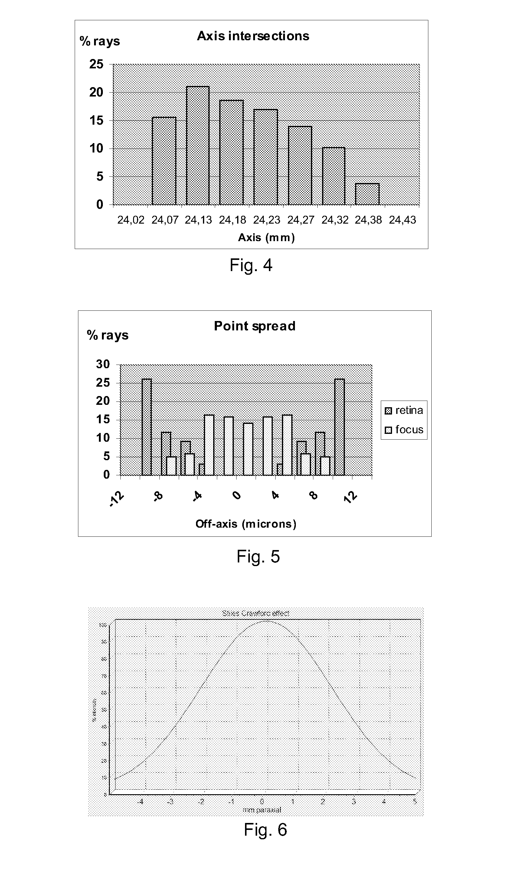
[0206]Further ray tracing examples show an eye of average dimension with a spherical IOL implanted to give good uncorrected vision at a negligible pupil size. The effective refraction has been plotted against the diameter of the pupil with and without correction for the Stiles-Crawford effect. FIG. 7 illustrates the effect of pupil size on the refraction predicted for a normal eye of average dimension with a spherical IOL implant. As the pupil widens, the eye becomes myopic as a result of spherical aberration. The effect is compensated for by the Stiles-Crawford effect (‘SC’). Two observations can be drawn from FIG. 7:[0207]1) The effective refraction is dependent on the pupil size also within the normal range (less than 3-4 mm), and[0208]2) The Stiles-Crawford effect compensates for the spherical aberration at larger pupil sizes.

example 3

Determination of IOL Power Actually Implanted (‘in situ’)

[0209]The refractive outcome (spectacle correction) of 53 eyes with an IOL implant with good postoperative visual acuity (>20 / 40) was evaluated. The cases were selected to cover a large range of IOL powers but otherwise randomly chosen from the consecutive series of lens surgeries performed at the Cataract Clinic, University of Aarhus, Denmark. The IOL implanted was an IOL of spherical design (Alcon SA60AT Acrysof) with a labelled power ranging from +2.0 to +40.0 D.

[0210]IOL Data

[0211]The assumed physical characteristics of the IOL (thickness, refractive index, front and back curvature were obtained from the ‘cutting chart’ provided by Alcon). The example of the cutting chart is given in the table 2.

TABLE 2‘Cutting’ chart provided from Alcon Laboratories showing the radii ofthe anterior and posterior surface of the IOL according to power.SA60AT & SN60ATDiopter RangeAnterior RadiiPosterior Radii 6.0-9.5 D35-81mm75.0 mm10.0-15.5...


PUM


Abstract

The present invention relates to a system and a method for determining the power of an artificial intraocular lens (IOL) in situ. The invention furthermore relates to a system and a method for predicting the optical outcome of IOL surgery. Use of the system may provide prevention, treatment, or amelioration of diseases and disorders affecting the lens of the eye and which may benefit from IOL surgery. Moreover, the invention relates to a computer-readable medium for implementing such a system on a computer.

Description

[0001]The present invention relates to a system and a method for determining the power of an artificial intraocular lens (IOL) in situ. The invention furthermore relates to a system and a method for predicting the optical outcome of IOL surgery. Use of the system may provide prevention, treatment, or amelioration of diseases and disorders affecting the lens of the eye and which may benefit from IOL surgery. Moreover, the invention relates to a computer-readable medium for implementing such a system on a computer.BACKGROUND OF INVENTION[0002]During cataract surgery (and other lens surgery) the ophthalmic surgeon extracts the biological crystalline lens and replaces it with an artificial intraocular lens (IOL). If the optical properties of the artificial implant match the optical properties and the dimensions of the eye, the patient has a good chance that the vision after surgery can be good without needing spectacles, irrespective of the need for spectacles before surgery. FIG. 20 sh...

Claims


Application Information

Patent Timeline
Patent Type & Authority Applications(United States)
IPC IPC(8): A61B3/10A61B3/107A61F2/16
CPCA61B3/0025A61B3/1015G06F19/3437G16H50/50
Inventor OLSEN, THOMAS
Owner IOL INNOVATIONS
Why Eureka
Try Eureka