Liquid crystal projector

a liquid crystal projector and projector technology, applied in lighting and heating apparatus, instruments, heating types, etc., can solve the problems of halogen lamps, source, large amount of heat, display properties deterioration, etc., to achieve the effect of preventing electrical failure, increasing the flow path of air which flows through the cooling medium, and reducing the amount of heat generated

Active Publication Date: 2011-10-06
SEIKO EPSON CORP
View PDF13 Cites 43 Cited by
  • Summary
  • Abstract
  • Description
  • Claims
  • Application Information

AI Technical Summary

Benefits of technology

[0012]According to the liquid crystal projector, water of air to be cooled by the thermoelectric conversion material is removed beforehand by the dehumidification device. Therefore, even though air sucked from the outside comes in contact with the low temperature section of the thermoelectric conversion material, the water of the air is almost completely removed by the dehumidification device, so that water is not condensed and dew condensation is not generated in the low temperature section of the thermoelectric conversion material. Therefore, the scattering of condensed water drops through the cooling medium flow path, the pollution of the light modulating device, and the generation of electrical failure can be reliably prevented.
[0013]It is preferable that the thermoelectric conversion element include the one side heat transmission plate exposed to the inside of the housing, and the other side heat transmission plate exposed to the outside of the housing. Therefore, the cooling efficiency of air which flows through the cooling medium flow path can be incre

Problems solved by technology

With respect to a lamp, for example, a halogen lamp, which is used for a light source, generates a large amount of heat when the light source light is irradiated.
Therefore, when a liquid crystal panel exceeds an allowable temperature due to the strong heat of a light source, display properties deteriorate and the life span thereof becomes short.
However, if the amount of blowing is increased by increasing the rotation speed of a cooling fan or the size of the fan with the increase in the output of the light source lamp as described above, the noise or the vibration of the liquid crystal projector increases, so that the

Method used


Image

  • Liquid crystal projector
  • Liquid crystal projector
  • Liquid crystal projector

Examples


Embodiment Construction

[0023]Hereinafter, a liquid crystal projector according an embodiment of the present invention will be described with reference to the accompanying drawings. Meanwhile, the present embodiment is described in detail in order to understand the gist of the invention better, and does not limit the invention unless otherwise stated. Further, with respect to the drawings which will be used for description below, an important part may be enlarged and then illustrated for convenience in order to facilitate understanding of the feature of the invention, and the ratio of the dimensions of each component is not limited to be the same as in reality.

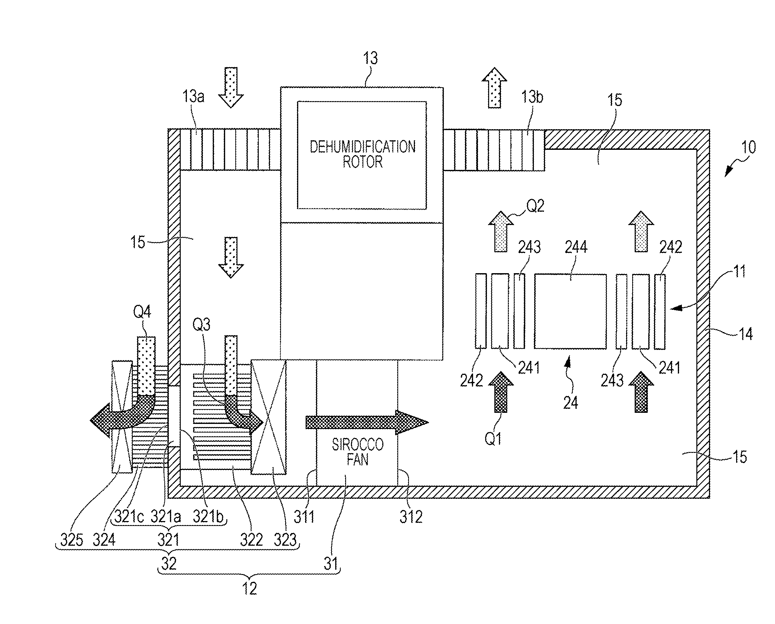
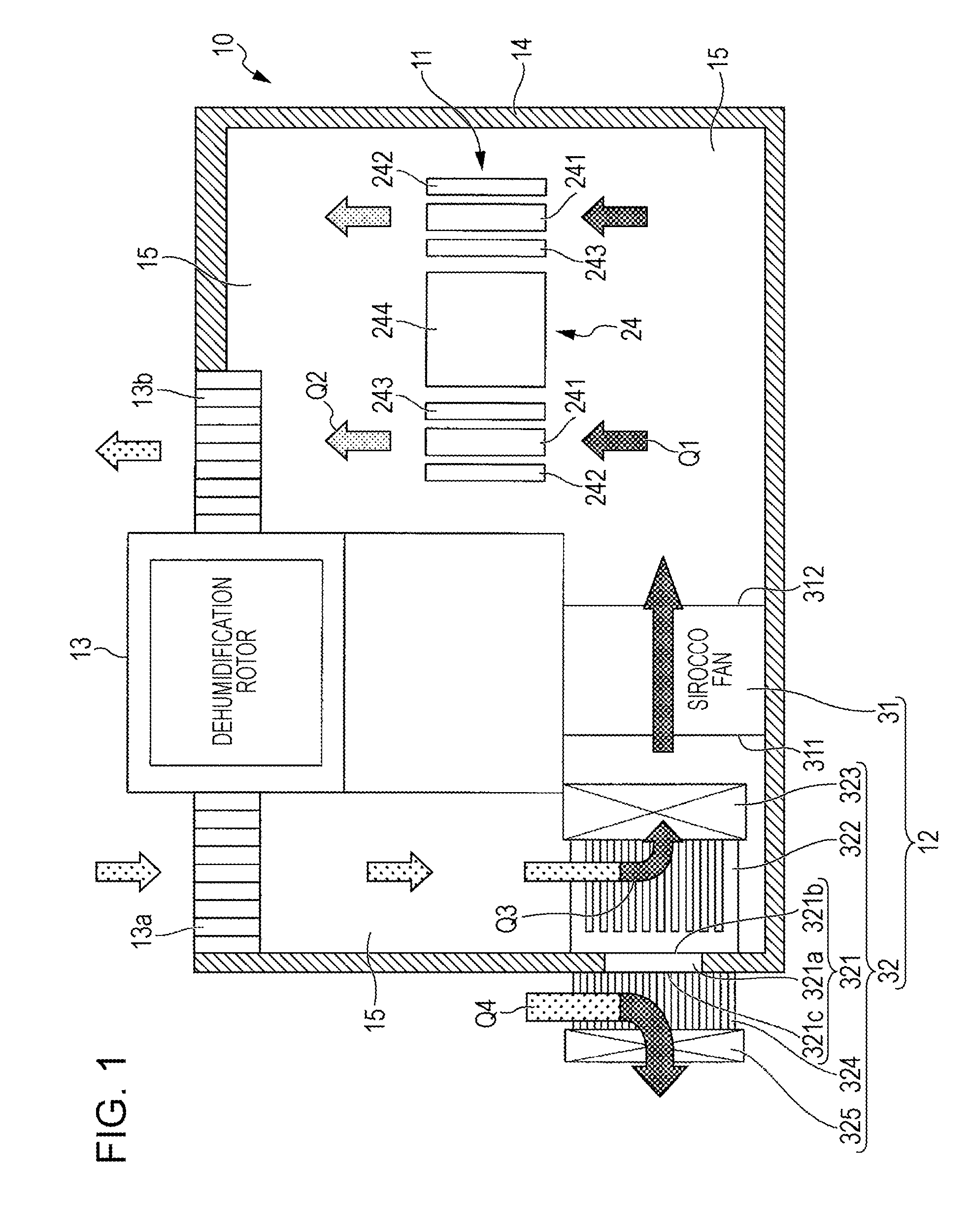
[0024]FIG. 1 is a cross-sectional view illustrating the outline of a liquid crystal projector according to an embodiment of the invention.

[0025]A liquid crystal projector 10 includes a light modulating device 11, a cooling device 12, a dehumidification device 13, and a housing 14 that accommodates the light modulating device 11, the cooling device 12...


PUM


Abstract

A liquid crystal projector includes a light modulating device, a cooling device, a dehumidification device, and a housing. The light modulating device forms an optical image by modulating light flux emitted from a light source based on image information. The cooling device cools air to be supplied to the light modulating device. The dehumidification device dehumidifies and dries air to be supplied to the corresponding cooling device. The housing includes a cooling medium flow path for circulating air among the light modulating device, the cooling device, and the dehumidification device. The cooling device includes a thermoelectric conversion material interposed between a pair of heat transmission plates arranged to face each other.

Description

BACKGROUND[0001]1. Technical Field[0002]The present invention relates to a liquid crystal projector that enlarges and displays images on a screen or the like, and, more particular, to a cooling technique of a liquid crystal projector.[0003]2. Related Art[0004]In a projection liquid crystal projector of the related art, an optical image (image light) is formed by a light modulating device, for example, a liquid crystal panel, that modulates light flux emitted from a light source based on image information, and an image is displayed by projecting the image light on a screen or the like. With respect to a lamp, for example, a halogen lamp, which is used for a light source, generates a large amount of heat when the light source light is irradiated. Therefore, when a liquid crystal panel exceeds an allowable temperature due to the strong heat of a light source, display properties deteriorate and the life span thereof becomes short.[0005]In particular, in recent years, there is a tendency...

Claims


Application Information

Patent Timeline
IPC IPC(8): G03B21/16
CPCF24F2203/1032H04N9/3197H04N9/3144G03B21/16
Inventor TERAO, KOICHI
Owner SEIKO EPSON CORP
Why Eureka
Try Eureka