Filter, coherent receiver device and coherent receiving method

a receiver device and receiver technology, applied in the field of filters and coherent receiver devices, can solve the problems of inability to directly use the coherent receiver in the conventional technique, the pre-filter device in the conventional technique is relatively complicated, and the coherent receiver device provided with respect to the pr-qam optical communication system does not adopt adaptive equalization techniques, etc., to achieve the effect of easy and reliable processing linear damage, low cost and simple structur

Active Publication Date: 2011-10-06
FUJITSU LTD
View PDF5 Cites 27 Cited by
  • Summary
  • Abstract
  • Description
  • Claims
  • Application Information

AI Technical Summary

Benefits of technology

[0024]In the coherent receiver device and the coherent receiving method according to the embodiments of the present invention, since the pre-filter according to the embodiments of the present invention is used, CMA and its improved equalization algorithm can be adopted, so as to easily and reliably process the linear damage caused by the link. In addition, the structure is very simple and the cost is low.
[0025]The coherent receiver according to the embodiments of the present invention places the phase recovering module between the pre-filter and the post-filter, so as to consider the function of phase recovery, and a feedback system (e.g., the phase lock loop in the simulation domain) is no longer required for the phase recovery. In addition, the complexity of the phase recovering device is maintained low.
[0026]In addition, the method and device (filter and coherent receiver) of the present invention are suitable to any appropriate system using PR-QAM, including various partial response types and QAM of various scales, thus they have a very good universality.

Problems solved by technology

Currently, the coherent receiver device provided with respect to the PR-QAM optical communication system does not adopt adaptive equalization technique.
However, the constant modulus algorithm (CMA) or its improved equalization algorithm commonly used in the coherent receiver cannot be directly used in the PR-QAM system.
But due to the defect caused by the loop-delay of the phase lock loop, the equalization is generally expected to be performed in the optical communication system prior to the phase recovery in the digital domain.
In addition, the pre-filter device in the conventional technique is relatively complicated, which increases the complexity of hardware.

Method used


Image

  • Filter, coherent receiver device and coherent receiving method
  • Filter, coherent receiver device and coherent receiving method
  • Filter, coherent receiver device and coherent receiving method

Examples


Embodiment Construction

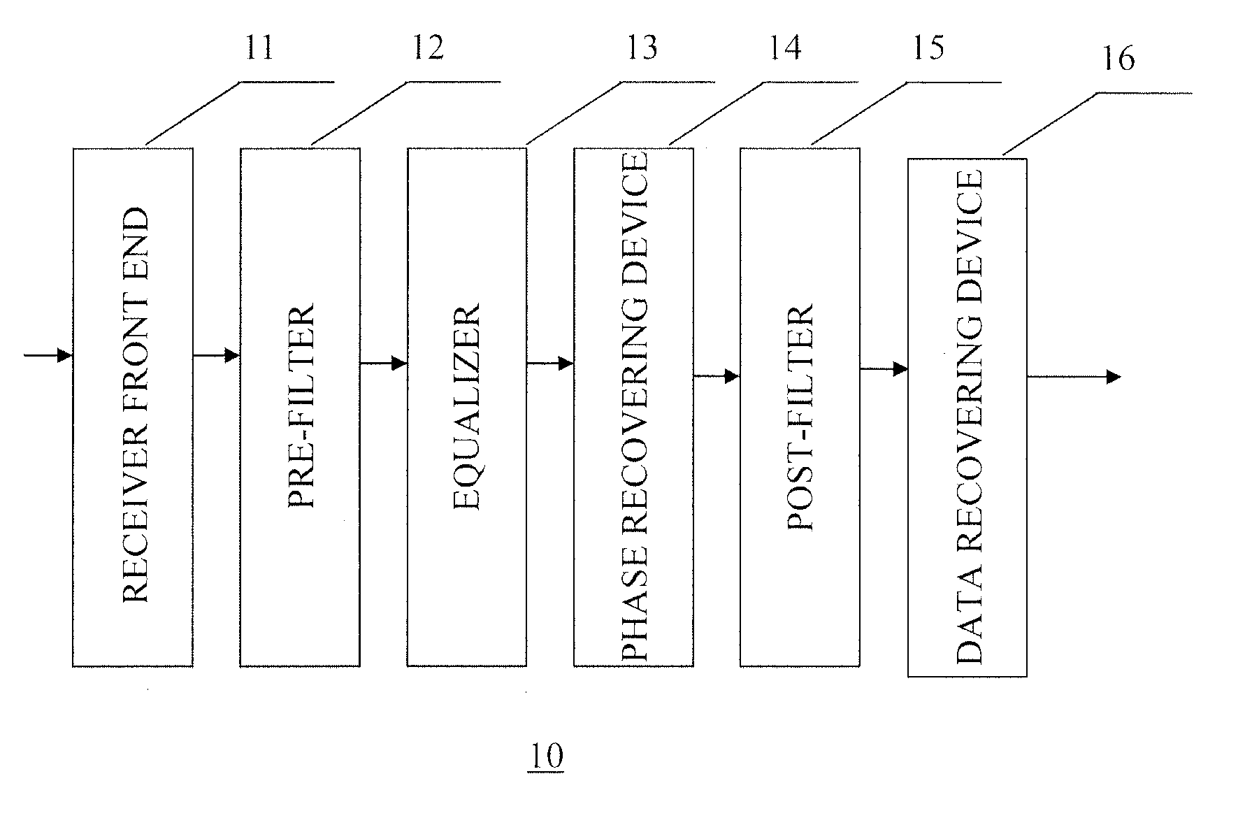
[0036]Descriptions of respective embodiments of the present invention are given as follows in conjunction with the drawings. These embodiments are just exemplary, instead of limitations to the present invention. In order that a person skilled in the art can easily understand the principle and embodiments of the present invention, the embodiments of the present invention are described by taking the optical communication system as an example. To be noted, the embodiments of the present invention are suitable to all communication systems using PR-QAM modulation format, and are not limited to the optical communication system.

[0037]FIG. 1 illustrates a schematic diagram of a coherent optical receiver device according to an embodiment of the present invention. To be noted, other components which are necessary for the receiver to complete its functions but not so helpful to describe and understand the present invention are omitted in the drawings. These omitted components can be implemente...


PUM


Abstract

The present invention relates to filter, coherent receiver device and coherent receiving method. The filter is used for converting a partial response signal into a full response signal, wherein the filter uses the following transfer function HPre-Filter(z) with respect to a partial response signal having a transfer function
HPR(z)=A(1+z-1)m(1-z-1)n:HPre-Filter(z)=1A(1+αz-1)m(1-αz-1)n,
in which A is other item, m and n are integers larger than or equal to 0 but not being 0 at the same time, 0<α<1.

Description

FIELD OF THE INVENTION[0001]The present invention relates to a filter, coherent receiver device and method, and particularly, to a pre-filter, coherent receiver device and coherent receiving method of Partial Response Quadrature Amplitude Modulation (PR-QAM) system.BACKGROUND OF THE INVENTION[0002]The optical fiber transmission system of low cost and high capacity is the development direction in the future optical communication. In order to further reduce the cost of single bit transportation and improve the capacity of single optical fiber, using the advanced modulation format having more compact spectrum is a good solution. The Partial Response Quadrature Amplitude Modulation (PR-QAM) is also called as Quadrature Partial Response (QPR) system, as it has a high spectral efficiency, related studies have been carried out in the field of optical communication. PR-QAM is a modulation format that combines the characteristics of the partial response and the quadrature amplitude modulatio...

Claims


Application Information

Patent Timeline
Patent Type & Authority Applications(United States)
IPC IPC(8): H04B10/06H04J14/06H04B10/61H04B10/516H04B10/532H04B10/54H04B10/556H04B10/58
CPCH04B10/611H04B10/614H04L27/3818H04L25/0305H04L25/03019H04B10/65
Inventor LI, JIANQIANGZHANG, HUIJIANTAO, ZHENNINGTANIMURA, TAKAHITO
Owner FUJITSU LTD
Why Eureka
Try Eureka