
Glass substrate polishing method, package manufacturing method, piezoelectric vibrator, oscillator, electronic device and radio timepiece

a technology of piezoelectric vibrator and polishing method, which is applied in the direction of manufacturing tools, generators/motors, lapping machines, etc., can solve the problems of deterioration in the vibration characteristics of piezoelectric vibrator, the inability to maintain the inability to secure the air tightness in the cavity, so as to improve the surface accuracy of the bonding surface and maintain the effect of air tightness

Inactive Publication Date: 2011-10-13
SEIKO INSTR INC
View PDF3 Cites 5 Cited by
  • Summary
  • Abstract
  • Description
  • Claims
  • Application Information

AI Technical Summary

Benefits of technology

The invention provides a glass substrate polishing method, a package manufacturing method, a piezoelectric vibrator, an oscillator, an electronic device, and a radio timepiece that can improve surface accuracy and maintain airtightness in a bonding area. The method includes a first polishing process using a polishing cloth and a second polishing process using urethane foam, which can remove surface sag and achieve a flat surface. The method also includes a two-sided polishing device that can simultaneously improve surface accuracy of both the front and rear surfaces of the glass substrate. The invention provides a solution for improving the bonding accuracy of electronic components in a package manufacturing process.

Problems solved by technology

As a result of this, the bonding area with the base substrate becomes smaller, and there is a possibility that the airtightness in the cavity cannot be maintained.
More specifically, when it is attempted to bond the two substrates, airtightness in the cavity cannot be secured due to a gap created between the bonding surfaces of the respective substrates, and there is a possibility of deterioration in vibration characteristics of the piezoelectric vibrator.

Method used


Image

  • Glass substrate polishing method, package manufacturing method, piezoelectric vibrator, oscillator, electronic device and radio timepiece
  • Glass substrate polishing method, package manufacturing method, piezoelectric vibrator, oscillator, electronic device and radio timepiece
  • Glass substrate polishing method, package manufacturing method, piezoelectric vibrator, oscillator, electronic device and radio timepiece

Examples


Embodiment Construction

[0058]Hereinafter, an embodiment of the invention will be described based on the drawings.

(Piezoelectric Vibrator)

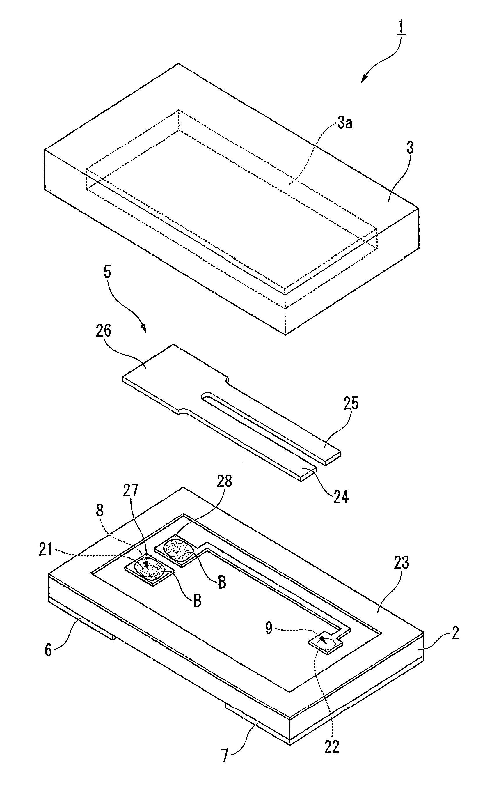
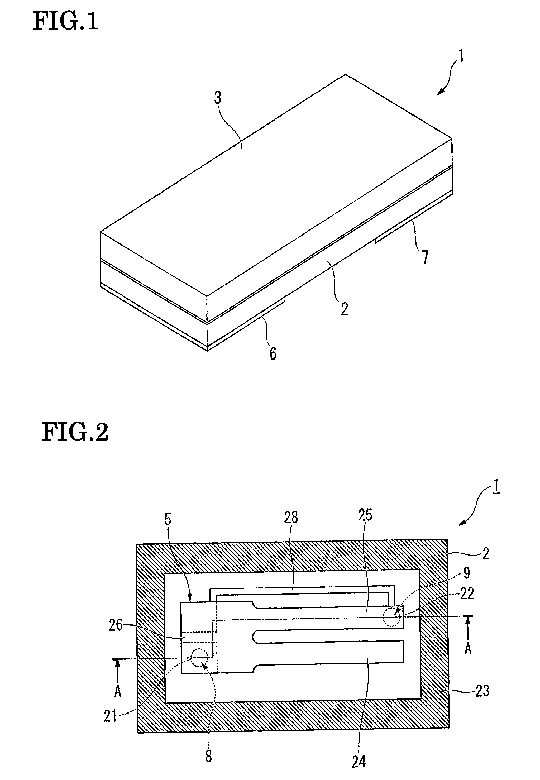
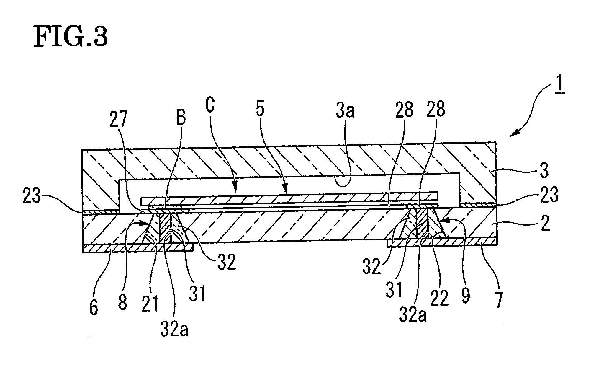
[0059]FIG. 1 is an external perspective view of a piezoelectric vibrator according to the embodiment. FIG. 2 is an internal structural view of the piezoelectric vibrator, and is a view showing a piezoelectric vibrating reed when viewed from above in a state in which a lid substrate is removed. Further, FIG. 3 is a cross-sectional view of the piezoelectric vibrator taken along a line A-A shown in FIG. 2, and FIG. 4 is an exploded perspective view of the piezoelectric vibrator.

[0060]As shown in FIG. 1 to FIG. 4, a piezoelectric vibrator 1 is formed in a box shape such that a base substrate 2 and a lid substrate 3 are laminated in two layers, and is the surface mount type piezoelectric vibrator 1 in which a piezoelectric vibrating reed 5 is housed in an internal cavity C. The piezoelectric vibrating reed 5 and external electrodes 6, 7 that are arranged on an outside of the ...


PUM

PropertyMeasurementUnit
Flow rateaaaaaaaaaa
voltageaaaaaaaaaa
resonance frequenciesaaaaaaaaaa

Abstract

A glass substrate polishing method having polishing processes for polishing a glass substrate surface while supplying a polishing agent. The glass substrate polishing method is characterized in that the polishing processes include a first polishing process in which the surface of the glass substrate is polished using a first polishing pad made from a polishing cloth and a second polishing process in which the surface of the glass substrate is polished using a second polishing pad made from urethane foam.

Description

RELATED APPLICATIONS[0001]This application is a continuation of PCT / JP2009 / 053332 filed on Feb. 25, 2009. The entire content of this application is incorporated herein by reference.BACKGROUND OF THE INVENTION[0002]1. Field of the Invention[0003]The present invention relates to a glass substrate polishing method, a package manufacturing method, a piezoelectric vibrator, an oscillator, an electronic device and a radio timepiece.[0004]2. Description of the Related Art[0005]In recent years, mobile telephones and portable information terminal devices employ a piezoelectric vibrator that uses crystal or the like as a time source, a timing source of control signals or the like, and a reference signal source etc. Various examples of this type of piezoelectric vibrator are known. One known example is a surface mount device (SMD) type piezoelectric vibrator. This type of piezoelectric vibrator includes, for example, a base substrate and a lid substrate that are bonded to each other, a cavity ...

Claims


Application Information

Patent Timeline
Patent Type & Authority Applications(United States)
IPC IPC(8): H03B5/36H01L41/22H01L41/053B24B1/00B24B37/08H01L41/23
CPCC03C19/00B24B37/08Y10T29/42H03H9/1021
Inventor FUJIHIRA, YOUICHISUGAMA, KAZUYOSHI
Owner SEIKO INSTR INC
Learn More