Wireless Sensing Module and Method of Operation

Inactive Publication Date: 2011-10-13
GREEN SHM SYST
View PDF18 Cites 126 Cited by
  • Summary
  • Abstract
  • Description
  • Claims
  • Application Information

AI Technical Summary

Benefits of technology

[0015]The present invention discloses wireless sensing modules with extended service life and method of operation. Wireless sensing modules according to the current invention are capable of operating for a long period of time because they harvest energy from the environment, utilize microcontrollers and employ algorithms, which allow for switching bet

Problems solved by technology

As wireless sensors can be installed in hard-to-get places, their maintenance can be expensive.
However, even if current consumption is as small as 1 mA and the sensor has two D-size batteries with total capacity of 40,000 mAh then the sensor will consume all the energy within 40,000 hours or approximately 4.5 years.
Consequently, service life of a wireless sensor with continuous operation is typically significantly shorter than 1 year and this is not acceptable in many application areas.
Unfortunately, efforts related to combining wireless sensors with energy harvesting devices did not yield any wireless sensing devices capable of operating for 10-15 years.
One is related to the small amounts of energy produced by the energy harvesting devices and some loss of harvested energy due to conditioning to a form suitable for use by wireless sensors.
The other reason is related to insufficient attention to long-term reliability of the energy harvesting devices and the wireless sensors themselves in field conditions.
However, it also has significant disadvantages.
A related issue—significant long-term drift of sensor parameters also can not be detected.
Besides that, power consumption by the sensor itself can be large enough to cause discharge of the battery within a relatively short period of time without the use of the radio.
However, in many cases using of just this approach is not enough.
In particular, if a wireless sensor consumes more than 0.1% of battery power

Method used


Image

  • Wireless Sensing Module and Method of Operation
  • Wireless Sensing Module and Method of Operation
  • Wireless Sensing Module and Method of Operation

Examples


first embodiment

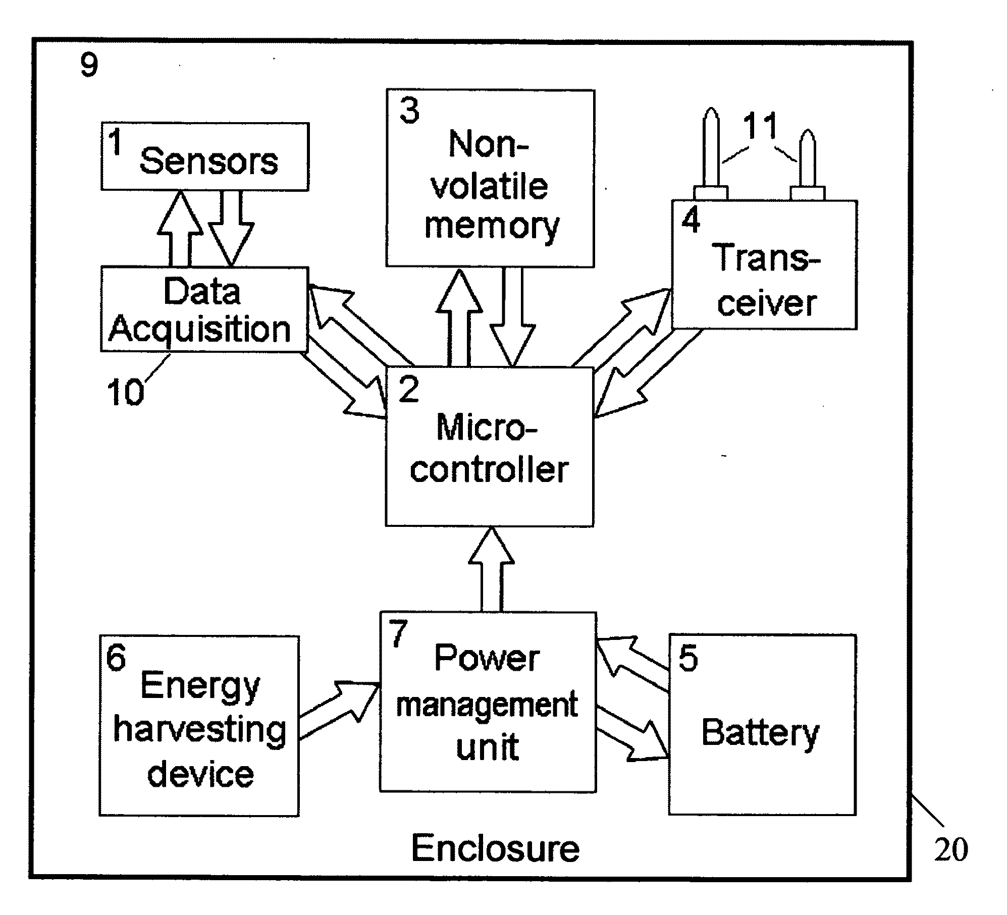
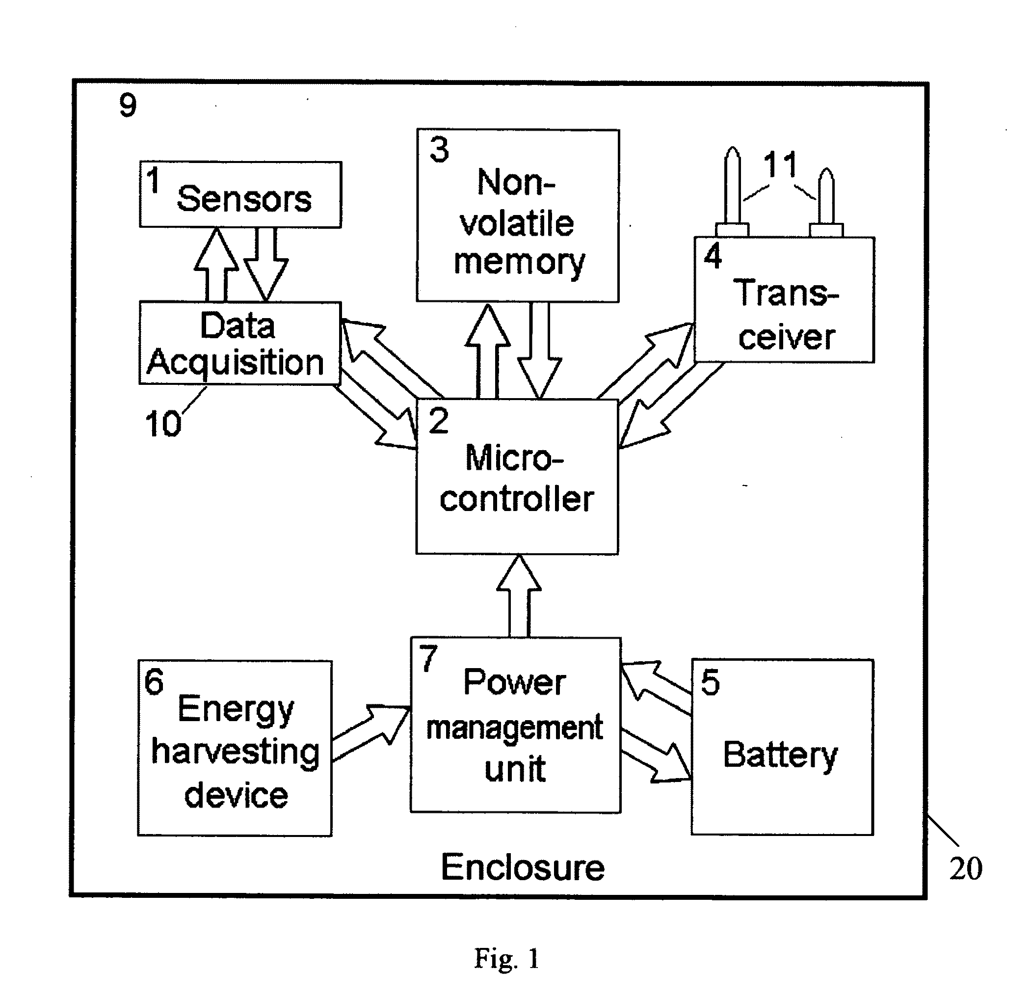
[0023]FIG. 1 shows a block diagram of a wireless sensing module 20 according to the present invention. The wireless sensing module 20 comprises a set of sensors 1, including at least one sensor of a physical parameter, a microcontroller 2, a non-volatile memory 3, a transceiver 4 with at least one antenna 11 and data acquisition hardware 10. The wireless sensing module 20 is powered by at least one battery 5. In many cases it is preferable to use several batteries 5. At least one battery providing power to the wireless sensing module 20 is a rechargeable or secondary battery. The wireless sensing module 20 also contains an energy harvesting device 6, which can harvest some energy from the environment. The harvested energy is transformed to electrical energy by this device and the output voltage is supplied to the power management unit 7. The power management unit 7 or power management circuit conditions the output voltage of the energy harvesting device 6 and uses the conditioned si...

second embodiment

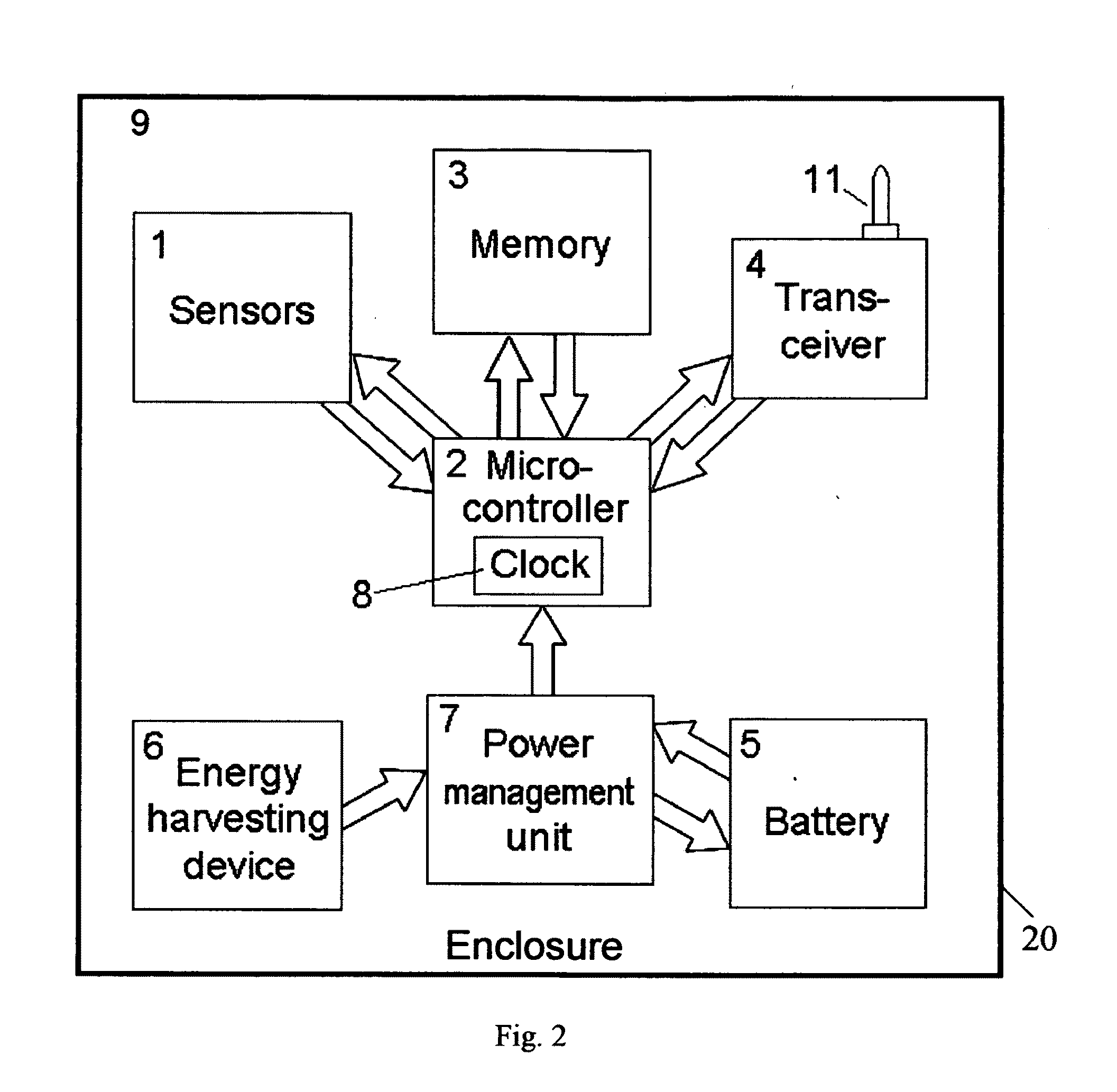
[0038]FIG. 2 shows a block diagram of a wireless sensing module 20 according to the present invention.

[0039]The wireless sensing module 20 contains a set of digital sensors 1 containing at least one digital sensor of a physical parameter, a microcontroller 2, a non-volatile memory 3, and a transceiver 4 with at least one antenna 11. Microcontroller 8 is used to generate a sleep-mode clock, which is used to wake up microcontroller. The wireless sensing module 20 is powered by at least one battery 5. At least one battery providing power to the wireless sensing module 20 is a rechargeable or secondary battery. The wireless sensing module 20 also contains an energy harvesting device 6. The output voltage of the energy harvesting device is conditioned by the power management unit 7 and used to charge the battery 5. The sensors 1, the microcontroller 2 with sleep-mode clock 8, the non-volatile memory 3, the transceiver 4, at least one battery 5, at least one energy harvesting device 6, th...

third embodiment

[0041]FIG. 3 shows a block diagram of a wireless sensing module 20 according to the present invention. The wireless sensing module 20 contains a set of sensors 1 containing at least one sensor of a physical parameter located inside the enclosure 9 and at least one external sensor 31 of a physical or a chemical parameter located outside the enclosure 9, a microcontroller 2, a non-volatile memory 3, data acquisition hardware 10, and a transceiver 4 with at least one antenna 11. The wireless sensing module 20 is powered by at least one battery 5. At least one battery providing power to the wireless sensing module 20 is a rechargeable or secondary battery. The wireless sensing module 20 also contains at least one energy harvesting device 6 either located inside the enclosure or embedded in it and at least one external energy harvesting device 36. The output voltage of energy harvesting devices is conditioned by the power management unit 7 and used to charge the battery 5. The sensors 1,...


PUM


Abstract

A wireless sensing module with extended service life containing at least one sensor of a physical parameter, a data acquisition hardware acquiring output electrical signals from at least one sensor and converting it into digital measurement data, a microcontroller, a non-volatile memory, at least one transceiver for wireless communication with external wireless devices, at least one battery, including at least one re-chargeable battery, at least one energy harvesting device, a power management circuit, and at least one antenna. All components of the wireless sensing module are mounted on a printed circuit board and placed into an enclosure providing mechanical, chemical, electrical and environmental protection. The wireless sensing modules can be used in different applications, including long-term condition monitoring of structures.

Description

BACKGROUND[0001]1. Field of the Invention[0002]This invention is related to wireless sensors and, more specifically, to wireless sensing modules with extended service life. The wireless sensing modules can be used in different applications, including long-term monitoring of structures and environmental monitoring.[0003]2. Description of Related Art[0004]Wireless sensors are currently being used in a wide range of applications and new application areas are emerging every year. One of the greatest advantages of wireless sensors is related to their ability to transfer measurement data and / or processed information via wireless links making wired connections to the sensors unnecessary. Using wireless communications greatly reduces the cost of sensor installation, allows for placing sensors on moving objects, for example, on rotating parts of machines, implanting them in live objects, etc. In most applications where wireless sensors are being used it is important not to have power deliver...

Claims


Application Information

Patent Timeline
IPC IPC(8): G08B1/08
CPCH04Q2209/886H04Q9/00G01N33/0075H04Q2209/86
Inventor BELOV, NICKOLAITCHELEPI, GHASSAN
Owner GREEN SHM SYST
Why Eureka
Try Eureka