Passive transmitter architecture with switchable outputs for wireless applications

a wireless transceiver and passive transmitter technology, applied in the field of wireless transceivers, can solve the problems of insufficient research and development efforts, large silicon area of the transceiver chip, and inconvenient us

Active Publication Date: 2011-10-13
ICERA INC
View PDF22 Cites 18 Cited by
  • Summary
  • Abstract
  • Description
  • Claims
  • Application Information

AI Technical Summary

Benefits of technology

[0008]It is an object of the present invention to obviate or mitigate at lea

Problems solved by technology

Under tremendous pressure to ship products as quickly as possible to the market, these products lack sufficient research and development efforts, and consequently the IC is either not competitive on silicon area and/or power consumption.
This results in larger

Method used


Image

  • Passive transmitter architecture with switchable outputs for wireless applications
  • Passive transmitter architecture with switchable outputs for wireless applications
  • Passive transmitter architecture with switchable outputs for wireless applications

Examples


Embodiment Construction

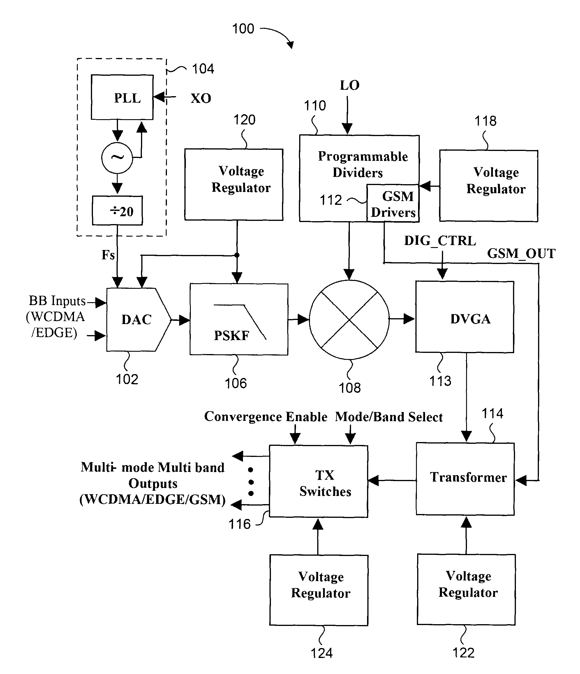
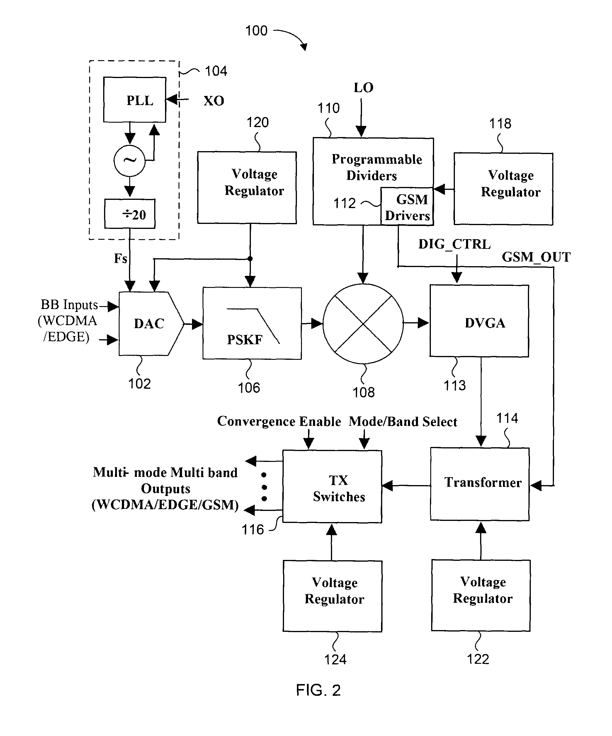
[0030]The present invention provides a fully integrated, low cost and SAW-less transmitter core for WCDMA / EDGE / GSM applications. The design uses a single path or set of hardware to realize multi-mode and multi-band functionality for WCDMA / EDGE / GSM applications. A multi-mode and multi-band transmitter is referred to as a multi-standard transceiver. Since the single path is reused for different modes and bands, minimum silicon area is consumed. A passive mixer using native devices enables low voltage design, and at the same time achieves low output noise and high linearity. A digital variable gain amplifier (DVGA) has the capability to cover a wide output dynamic range while operated from a low supply voltage and under the control of the baseband circuit without any intervening digital to analog converter (DAC). The output power of the DVGA changes linearly in dB with respect to the input codes through sizing of the transistors and / or manipulating of the bias current. A single transfo...


PUM


Abstract

A transmitter architecture having a single signal path or hardware to cover WCDMA/EDGE/GSM applications, and requires no SAW at the transmitter outputs. The transmitter architecture allows for a transmit convergence feature. A passive mixer with unique driver and furthermore using native devices available from the CMOS process for the mixer cores enables low voltage and low power design, low output noise and high linearity. A digital variable gain amplifier has the capability to cover wide output dynamic range operated from low supply voltage and interfaced digitally with the baseband circuit without DAC. A single transformer is used to combine the outputs from the WCDMA/EDGE and GSM drivers and subsequently convert the differential signal paths into a single-ended signal. RF switches are used to divert the output from the transformer to different bands and applications.

Description

CROSS REFERENCE TO RELATED APPLICATIONS[0001]This application claims the benefit of priority of U.S. Provisional Patent Application No. 61 / 094,713 filed on Sep. 5, 2008, which is incorporated herein by reference in its entirety.FIELD OF THE INVENTION[0002]The present invention relates generally to wireless transceivers. More particularly, the present invention relates a transmitter circuit of a wireless transceiver.BACKGROUND OF THE INVENTION[0003]Wireless devices have been in use for many years for enabling mobile communication of voice and data. Such devices can include mobile phones and wireless enabled personal digital assistants (PDA's) for example. FIG. 1 is a generic block diagram of the core components of such wireless devices. The wireless core 10 includes a base band processor 12 for controlling application specific functions of the wireless device and for providing and receiving voice or data signals to a radio frequency (RF) transceiver chip 14. The RF transceiver chip 1...

Claims


Application Information

Patent Timeline
IPC IPC(8): H04B1/04
CPCH03F1/0261H03G3/001H03F3/195H03F3/211H03F3/245H03F3/45188H03F3/45659H03F3/72H03F2200/372H03F2200/451H03F2200/541H03F2203/21142H03F2203/21175H03F2203/21178H03F2203/45418H03F2203/45424H03F2203/45544H03F2203/45634H03F2203/45726H03F2203/7236H03F1/0277
Inventor BELLAOUAR, ABDELLATIFLEE, SEE TAURFANG, SHER JIUNEMBABI, SHERIF H.K.MANKU, TAJINDER
Owner ICERA INC
Why Eureka
Try Eureka